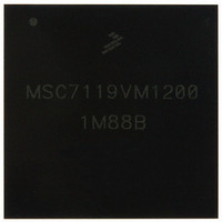
KMSC7119VM1200 Freescale Semiconductor, KMSC7119VM1200 Datasheet - Page 21

KMSC7119VM1200
Manufacturer Part Number
KMSC7119VM1200
Description
DSP 16BIT W/DDR CTRLR 400-MAPBGA
Manufacturer
Freescale Semiconductor
Series
MSC711x StarCorer
Type
Fixed Pointr
Datasheet
1.MSC7119VF1200.pdf
(60 pages)
Specifications of KMSC7119VM1200
Interface
Host Interface, I²C, UART
Clock Rate
300MHz
Non-volatile Memory
ROM (8 kB)
On-chip Ram
464kB
Voltage - I/o
3.30V
Voltage - Core
1.20V
Operating Temperature
-40°C ~ 105°C
Mounting Type
*
Package / Case
400-MAPBGA
Lead Free Status / RoHS Status
Lead free / RoHS Compliant
Available stocks
Company
Part Number
Manufacturer
Quantity
Price
Company:
Part Number:
KMSC7119VM1200
Manufacturer:
Freescale Semiconductor
Quantity:
10 000
2.5
This section presents timing diagrams and specifications for individual signals and parallel I/O outputs and inputs. All AC
timings are based on a 30 pF load, except where noted otherwise, and a 50 Ω transmission line. For any additional pF, use the
following equations to compute the delay:
2.5.1
The following tables describe clock signal characteristics. Table 6 shows the maximum frequency values for internal (core,
reference, and peripherals) and external (
Section 2.5.2 for the allowable ranges when using the PLL).
Freescale Semiconductor
Core clock frequency (CLOCK)
External output clock frequency (CLKO)
Memory clock frequency (CK, CK)
TDM clock frequency (TxRCK, TxTCK)
CLKIN frequency
CLOCK frequency
CK, CK frequency
TDMxRCK, TDMxTCK frequency
CLKO frequency
AHB/IPBus/APB clock frequency
Note:
CLKIN frequency
CLKIN slope
CLKIN frequency jitter (peak-to-peak)
CLKO frequency jitter (peak-to-peak)
— Standard interface: 2.45 + (0.054 × C
— DDR interface: 1.6 + (0.002 × C
The rise and fall time of external clocks should be 5 ns maximum
AC Timings
Clock and Timing Signals
Characteristic
Characteristic
Characteristic
CLKO
Table 7. Clock Frequencies in MHz
Table 8. System Clock Parameters
Table 6. Maximum Frequencies
load
) clocks. You must ensure that maximum frequency values are not exceeded (see
MSC7119 Data Sheet, Rev. 8
) ns
load
) ns
Symbol
F
F
F
F
TDMCK
F
Min
CLKIN
CORE
F
CKO
BCK
10
—
—
—
CK
Maximum in MHz
300
150
75
50
Max
1000
Min
100
150
10
—
—
—
—
—
5
Electrical Characteristics
Max
Unit
MHz
100
300
150
150
50
75
ns
ps
ps
21


