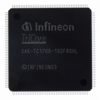
SAK-TC1766-192F80HL BD Infineon Technologies, SAK-TC1766-192F80HL BD Datasheet - Page 90

SAK-TC1766-192F80HL BD
Manufacturer Part Number
SAK-TC1766-192F80HL BD
Description
IC MCU 32BIT FLASH PG-LQFP-176
Manufacturer
Infineon Technologies
Series
TC17xxr
Datasheet
1.SAK-TC1766-192F80HL_BD.pdf
(117 pages)
Specifications of SAK-TC1766-192F80HL BD
Core Processor
TriCore
Core Size
32-Bit
Speed
80MHz
Connectivity
ASC, CAN, MLI, MSC, SSC
Peripherals
DMA, POR, WDT
Number Of I /o
81
Program Memory Size
1.5MB (1.5M x 8)
Program Memory Type
FLASH
Ram Size
108K x 8
Voltage - Supply (vcc/vdd)
1.42 V ~ 1.58 V
Data Converters
A/D 2x10b; A/D 32x8b,10b,12b
Oscillator Type
External
Operating Temperature
-40°C ~ 125°C
Package / Case
176-LFQFP
Packages
PG-LQFP-176
Max Clock Frequency
80.0 MHz
Sram (incl. Cache)
108.0 KByte
Can Nodes
2
A / D Input Lines (incl. Fadc)
36
Program Memory
1.5 MB
For Use With
B158-H8539-G2-X-7600IN - KIT STARTER TC176X SERIES
Lead Free Status / RoHS Status
Lead free / RoHS Compliant
Eeprom Size
-
Other names
KT1766192F80HLBDXT
SAK-TC1766-192F80HLBDINTR
SAK-TC1766-192F80HLBDINTR
Preliminary
Table 4-7
Parameter
Analog supply
currents
Input current at each
V
Input leakage current
at
Input leakage current
at
Conversion time
Converter Clock
Input resistance of
the analog voltage
path (Rn, Rp)
Channel Amplifier
Cutoff Frequency
Settling Time of a
Channel Amplifier
after changing ENN
or ENP
1) Calibration of the gain is possible for the gain of 1 and 2, and not possible for the gain of 4 and 8.
2) Callibration should be performed at each power-up. In case of continuous operation, callibration should be
3) The offset error voltage drifts over the whole temperature range typically ±2 LSB.
4) Applies when the gain of the channel equals one. For the other gain settings, the offset error increases; it must
5) The leakage current definition is a continuous function, as shown in
6) Only one of these parameters is tested, the other is verified by design characterization.
7) Voltage overshoot to 4 V are permissible, provided the pulse duration is less than 100 µs and the cumulated
8) Voltage overshoot to 1.7 V are permissible, provided the pulse duration is less than 100 µs and the cumulated
9) A running conversion may become inexact in case of violating the normal operating conditions (voltage
10) Current peaks of up to 40 mA with a duration of max. 2 ns may occur
Data Sheet
FAREF
V
V
performed minimum once per week.
be multiplied with the applied gain.
determine the characteristic points of the given continuous linear approximation - they do not define step
function.
summary of the pulses does not exceed 1 h.
sum of the pulses does not exceed 1 h.
overshoots).
FAREF
FAGND
11)
FADC Characteristics (cont’d)(Operating Conditions apply)
Symbol
I
I
I
I
I
t
f
R
f
t
C
ADC
COFF
SET
DDMF
DDAF
FAREF
FOZ2
FOZ3
FAIN
SR –
SR –
CC –
CC –
CC
CC –
CC –
CC 100
CC 2
CC
Min.
Limit Values
86
Max.
9
17
150
±500
±8
21
80
200
5
Figure
Unit
mA
mA
µA
rms
nA
µA
CLK of
f
MHz
kΩ
MHz
µsec
ADC
4-5. The numerical values defined
Electrical Parameters
Remarks
Conditions
–
10)
Independent of
conversion
0 V <
For 10-bit conv.
–
12)
–
–
V
IN
V1.0, 2008-04
<
V
TC1766
DDMF


