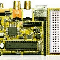
Chameleon-AVR Nurve Networks, Chameleon-AVR Datasheet - Page 129

Chameleon-AVR
Manufacturer Part Number
Chameleon-AVR
Description
MCU, MPU & DSP Development Tools AVR8 & PROPELLER DEV SYSTEM (SBC)
Manufacturer
Nurve Networks
Datasheet
1.CHAMELEON-AVR.pdf
(268 pages)
Specifications of Chameleon-AVR
Processor To Be Evaluated
AVR 328P
Data Bus Width
8 bit
Interface Type
USB, VGA, PS/2, I2C, ISP, SPI
Operating Supply Voltage
3.3 V, 5 V
Lead Free Status / RoHS Status
Lead free / RoHS Compliant
- Current page: 129 of 268
- Download datasheet (17Mb)
Table 16.1 shows the pin map in more detail.
16.1 Master Control Program (MCP)
The MCP (cham_default2_drv_112.spin) is the primary driver that runs on the Propeller chip and listens to SPI traffic
over the SPI link from the AVR chip as shown in Figure 16.2. As the virtual SPI interface (running on its own core)
receives packets (messages/commands) from the AVR, the messages are parsed and packaged and placed into a global
shared memory region. The MCP is listening to the global shared region and tracks a flag. Once this flag is noted to
change, the MCP reads the packet in and then tries to parse it to determine if it’s a valid command that is supported. This
is achieved via a large switch statement to see if the command portion of the packet is valid. Below is the list of current
commands supported by the MCP by the default driver cham_default2_drv_112.spin:
I/O device
NTSC video
VGA video
PS/2 Keyboard
Sound
Serial Coms
Table 16.1 - The I/O pin map for the connections to media devices.
Figure 16.2 – The SPI link between the AVR and Propeller chip.
Propeller IO Port Pins Used
12, 13, 14 (video LSB to MSB)
16(V),17(H),18(B1),19(B0),20(G1),21(G0),22(R1),23(R0)
26 (data), 27 (clock)
10 (PWM or pure signal)
30 (TX), 31 (RX)
© 2009 NURVE NETWORKS LLC “Exploring the Chameleon AVR 8-Bit”
129
Related parts for Chameleon-AVR
Image
Part Number
Description
Manufacturer
Datasheet
Request
R

Part Number:
Description:
MCU, MPU & DSP Development Tools PIC24 & PROPELLER DEV SYSTEM (SBC)
Manufacturer:
Nurve Networks
Datasheet:

Part Number:
Description:
MCU, MPU & DSP Development Tools AVR8 VIDEO GAME DEV SYSTEM (SBC)
Manufacturer:
Nurve Networks

Part Number:
Description:
MCU, MPU & DSP Development Tools PIC24 VIDEO GAME DEV SYSTEM (SBC)
Manufacturer:
Nurve Networks


