Chameleon-AVR Nurve Networks, Chameleon-AVR Datasheet - Page 155
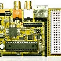
Chameleon-AVR
Manufacturer Part Number
Chameleon-AVR
Description
MCU, MPU & DSP Development Tools AVR8 & PROPELLER DEV SYSTEM (SBC)
Manufacturer
Nurve Networks
Datasheet
1.CHAMELEON-AVR.pdf
(268 pages)
Specifications of Chameleon-AVR
Processor To Be Evaluated
AVR 328P
Data Bus Width
8 bit
Interface Type
USB, VGA, PS/2, I2C, ISP, SPI
Operating Supply Voltage
3.3 V, 5 V
Lead Free Status / RoHS Status
Lead free / RoHS Compliant


19.1.1 Basic SPI Communications Steps
Figures 19.2(a) and (b) show the complete timing diagrams for all variants of clock polarity (CPOL) and clock phase
(CPHA). You must adhere to these timing constraints during communications. In most cases, you will use mode 0 since
it’s the default that most SPI devices boot with.
The good news is this is all taken care of by the AVR 328P, in fact, most AVR microcontrollers have complete SPI (and
I
programmers is set the hardware up, then send and receive bytes (and maybe handle an interrupt or two). Thus, working
with SPI in the AVR 328P is very easy. Nonetheless, the library module we developed wraps the SPI hardware with a thin
layer of functions, so that you don’t have to deal with it all yourself. However, it’s good to understand the protocol if you
need to manually build a SPI interface with I/O pins. For example, maybe you need (4) SPI interfaces all at the same time
on the Chameleon’s expansion port, the only way to do this will be to do it manually with pin toggling.
However, the AVR 328P’s USARTs (basically UARTs with extra features) both support “SPI modes”. In other words, even
though the AVR 328P has a primary SPI controller, the USART on the AVR 328P can be put into “SPI mode” as well,
giving you (2) fully functioning SPI devices, interrupt driven, etc. This is very good news. Moreover, the Chameleon’s
expansion headers port exports out the master SPI device itself as well as the ancillary SPI-mux selects.
Using the AVR SPI interface is straightforward, the steps are:
That’s all there is to it. Of course, there’s a lot of detail to getting things to work and believe me, I had my share of
frustration figuring out the little quirks, but the library functions provided shortly will get you up and running very quickly
with SPI interfacing. Also, you can always write you own, or use external libraries. The AVR Libc system does not have
any SPI library of note, but there are many out there like the Procyon library located here:
19.2 I
The I
signal lines (SDA – data, SCL – clock), thus more protocol and conventions must be adhered to, to deal with bus
contention etc., secondly I
superior for “daisy chaining” devices together with as well as cheaper. Of course, you never get something for nothing
2
C) hardware built in that take care of all the details of both transmission and reception. The only thing we have to do as
2
C bus is a little more complex that the SPI bus interface and protocol. The reason is that the I
2
Initialize the hardware (set speed, clock phase and polarity, etc.).
Send and receive bytes via a pair of registers (and possibly interrupts).
http://hubbard.engr.scu.edu/embedded/avr/avrlib/
http://ccrma.stanford.edu/courses/250a/docs/avrlib/html/index.html
http://ccrma.stanford.edu/courses/250a/docs/avrlib/html/install.html
C Bus Basics
Figure 19.2(b) – SPI timing diagrams for clock phase polarity (CPHA=1).
2
C supports up to 128 devices simultaneously connected to the bus! This feature makes I
© 2009 NURVE NETWORKS LLC “Exploring the Chameleon AVR 8-Bit”
2
C bus uses only 2
2
C
155
Related parts for Chameleon-AVR
Image
Part Number
Description
Manufacturer
Datasheet
Request
R

Part Number:
Description:
MCU, MPU & DSP Development Tools PIC24 & PROPELLER DEV SYSTEM (SBC)
Manufacturer:
Nurve Networks
Datasheet:

Part Number:
Description:
MCU, MPU & DSP Development Tools AVR8 VIDEO GAME DEV SYSTEM (SBC)
Manufacturer:
Nurve Networks

Part Number:
Description:
MCU, MPU & DSP Development Tools PIC24 VIDEO GAME DEV SYSTEM (SBC)
Manufacturer:
Nurve Networks