Chameleon-AVR Nurve Networks, Chameleon-AVR Datasheet - Page 72
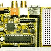
Chameleon-AVR
Manufacturer Part Number
Chameleon-AVR
Description
MCU, MPU & DSP Development Tools AVR8 & PROPELLER DEV SYSTEM (SBC)
Manufacturer
Nurve Networks
Datasheet
1.CHAMELEON-AVR.pdf
(268 pages)
Specifications of Chameleon-AVR
Processor To Be Evaluated
AVR 328P
Data Bus Width
8 bit
Interface Type
USB, VGA, PS/2, I2C, ISP, SPI
Operating Supply Voltage
3.3 V, 5 V
Lead Free Status / RoHS Status
Lead free / RoHS Compliant


Which in this example is,
So, you have two options; either increase the PWM frequency or index into your sample table at larger intervals. This
problem along with the lack of precision can be handled by use of fixed point arithmetic and a little numerical trick. We are
going to scale all the math by 8-bits or in essence multiply by 256 then we are going to create two variables one called a
phase accumulator (PHASE_ACC) and one called a phase increment (PHASE_INC). Then instead of using count down
algorithms, we are going to simply add the phase increment to the phase accumulator and use the phase accumulator as
an index into the sine table. Therefore, what we have done is turned out 256 element sine table into a “virtual” 256*256 =
65536 element sine table for math purposes to give us more accuracy for slower, non-integral waveforms as well as allow
fast waveforms to index and skip elements in the look up table, so a possible setup is something like this:
The Phase Accumulator 16-bit
Now, we have two interesting properties; first, no matter what the index in the upper 8-bits can never exceed 255, so we
can never go out of bounds of our table, secondly, we can put very small numbers into the phase accumulator via that
phase increment variable.
So now the algorithm for PWM sound is simple:
Step 1: Run the PWM at the output frequency 256,000 Hz.
Step 2: Calculate the Phase Increment (PHASE_INC) to add to the Phase Accumulator (PHASE_ACC) such that the final
desired “signal” frequency is output via the lookup into the sine or waveform table.
Step 3: Continually add the Phase Increment to the Phase Accumulator and every cycle use the upper 8-bits of the Phase
Accumulator as the index into the 256 element sine table.
Now, to recap, we still have a table that has only 256 elements, but we are going to pretend it has 65536 elements, that is,
256*256 to improve our accuracy, this is nothing more than using a shift << 8 and create a fixed point value in 8.8 format.
Next, we are going to call out a couple vars to make the algorithm easy, one is an accumulator called PHASE_ACC that
simply accumulates the current count then we convert it back to an integer by shifting it >> 8 times OR just using the
upper 8-bits at the index into our 256 element sine table (the later is preferred). Then we simply need the magic number
Maximum Synthesis Frequency = PWM frequency / Number of Samples per Cycle
256,000 / 256 = 1000 Hz
Figure 14.7 – Our final PWM setup.
© 2009 NURVE NETWORKS LLC “Exploring the Chameleon AVR 8-Bit”
72
Related parts for Chameleon-AVR
Image
Part Number
Description
Manufacturer
Datasheet
Request
R

Part Number:
Description:
MCU, MPU & DSP Development Tools PIC24 & PROPELLER DEV SYSTEM (SBC)
Manufacturer:
Nurve Networks
Datasheet:

Part Number:
Description:
MCU, MPU & DSP Development Tools AVR8 VIDEO GAME DEV SYSTEM (SBC)
Manufacturer:
Nurve Networks

Part Number:
Description:
MCU, MPU & DSP Development Tools PIC24 VIDEO GAME DEV SYSTEM (SBC)
Manufacturer:
Nurve Networks