Chameleon-AVR Nurve Networks, Chameleon-AVR Datasheet - Page 64
Chameleon-AVR
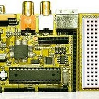
Manufacturer Part Number
Chameleon-AVR
Description
MCU, MPU & DSP Development Tools AVR8 & PROPELLER DEV SYSTEM (SBC)
Manufacturer
Nurve Networks
Datasheet
1.CHAMELEON-AVR.pdf
(268 pages)
Specifications of Chameleon-AVR
Processor To Be Evaluated
AVR 328P
Data Bus Width
8 bit
Interface Type
USB, VGA, PS/2, I2C, ISP, SPI
Operating Supply Voltage
3.3 V, 5 V
Lead Free Status / RoHS Status
Lead free / RoHS Compliant


Referring to the figure, there are two 8-pin I/O headers on the bottom of the board. A single 16-pin header on the right,
and finally the 8-bit Propeller local port. The Propeller local port is discussed elsewhere, so let’s concentrate on the other
3 headers. First off, on the Chameleon AVR version specifically we tried to map the Arduino compatible signal names to
the same pins on the 328P chip, so programs written for Arduinos’’’’’’’’’’’’’’’’’’’’’’’’’’’’’’’’’’’’’’’’’’’’’’’’’’’’’’’’’ that use digital I/O would
work with little modification. Similarly, we used the name naming conventions for the signals such as Dn for digital I/Os
and AINn for analog inputs. However, the Chameleon has a few extra signals mostly on the larger 16-pin header on the
right. Signals such as the multiple power sources as well as the SPI multiplexer chip selects SPI_SS1n and SPI_SS0n
respectively. Figure 13.2 below illustrates the electrical design of the headers themselves laid out as they are on the PCB.
Also, the pins on the headers obviously connect to multifunction pins such as the serial UARTS, SPI, and so forth. Table
13.1 below maps the header pin names to the physical pin names and numbers for your convenience.
I/O Header Designator
J5
J5
J5
J5
J5
J5
J5
J5
J4
J4
J4
J4
I/O Header Pin Name/#
AREF
GND
DPIN13
DPIN12
DPIN11
DPIN10
DPIN9
DPIN8
DPIN7
DPIN6
DPIN5
DPIN4
Figure 13.2 – I/O headers electrical design.
1
Table 13.1 – I/O header pinout map.
© 2009 NURVE NETWORKS LLC “Exploring the Chameleon AVR 8-Bit”
AVR Pin #
21
8, 22
19
18
17
16
15
14
13
12
11
6
AVR Pin Name/Extra Function
AREF
GND
PB5 (SCK / PCINT5)
PB4 (MISO / PCINT4)
PB3 (MOSI / OC2A / PCINT3)
PB2 (SSn / OC1B / PCINT2 )
PB1 (OCA1 / PCINT1)
PB0 (PCINT0 / CLK0 / ICP1)
PD7 (PCINT23 / AIN1)
PD6 (PCINT22 / OC0A / AIN0)
PD5 (PCINT21 / OCB0 / T1)
PD4 (PCINT20 / XCK / TO)
64
Related parts for Chameleon-AVR
Image
Part Number
Description
Manufacturer
Datasheet
Request
R

Part Number:
Description:
MCU, MPU & DSP Development Tools PIC24 & PROPELLER DEV SYSTEM (SBC)
Manufacturer:
Nurve Networks
Datasheet:

Part Number:
Description:
MCU, MPU & DSP Development Tools AVR8 VIDEO GAME DEV SYSTEM (SBC)
Manufacturer:
Nurve Networks

Part Number:
Description:
MCU, MPU & DSP Development Tools PIC24 VIDEO GAME DEV SYSTEM (SBC)
Manufacturer:
Nurve Networks