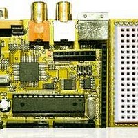
Chameleon-AVR Nurve Networks, Chameleon-AVR Datasheet - Page 24

Chameleon-AVR
Manufacturer Part Number
Chameleon-AVR
Description
MCU, MPU & DSP Development Tools AVR8 & PROPELLER DEV SYSTEM (SBC)
Manufacturer
Nurve Networks
Datasheet
1.CHAMELEON-AVR.pdf
(268 pages)
Specifications of Chameleon-AVR
Processor To Be Evaluated
AVR 328P
Data Bus Width
8 bit
Interface Type
USB, VGA, PS/2, I2C, ISP, SPI
Operating Supply Voltage
3.3 V, 5 V
Lead Free Status / RoHS Status
Lead free / RoHS Compliant
- Current page: 24 of 268
- Download datasheet (17Mb)
1.3 The Parallax Propeller Chip
The Parallax Propeller chip is a low cost multicore processor with a very simple design and programming model. Referring
to Figure 1.8 take a look at the block diagram of the chip. The Propeller chip consists of (8) symmetrical processing units
(cores) that are identical. Each core has a 32-bit CPU, 512 32-bit words of memory, a pair of counters and a crude video
streaming unit. The cores run at 80MHz nominal and take 4 clocks to execute an instruction. Therefore, each core is
capable of running at 20 MIPs. Additionally, each core has access to the 32 I/O pins of the chip as well as a shared 32K
Byte RAM and 32K Byte ROM. Access to the RAM is arbitrated by a “hub” that gives each core access to the RAM in lock
step, thus its impossible for one core to access RAM while another core is, thus, no potential for corruption of memory.
For complete details on the processor, please review the datasheet located on the DVD-ROM here:
Referring to the pinout of the Propeller as shown in Figure 1.9, the philosophy of the Propeller is to keep things really
simple; therefore, there are no peripherals (other than the video hardware) on the chip. The idea is that if you want a SPI
port, UART, D/A, A/D, etc. you will write one with pure software and run it on one of the cores as a “virtual peripheral”.
Therefore, chip space and silicon aren’t wasted on peripherals you will never use. Rather, the Propeller is 100%
programmable and you simply load peripherals as software.
As you can see, the Propeller chips have nothing more than power, reset, clock, and 32 I/O pins. There are no dedicated
peripherals whatsoever (actually, that’s not completely true – each core has video hardware).
Pin Name
P0 – P31
VDD
VSS
DVD-ROM: \ cham_avr \ docs \ datasheets \ PropellerDatasheet-v1.2.pdf
Direction
I/O
---
---
Description
General purpose I/O Port A. Can source/sink 40 mA each at 3.3 VDC. CMOS level logic with threshold of ≈ ½ VDD or
1.6 VDC @ 3.3 VDC.
The pins shown below have a special purpose upon power-up/reset but are general purpose I/O afterwards.
P28 - I2C SCL connection to optional, external EEPROM.
P29 - I2C SDA connection to optional, external EEPROM.
P30 - Serial Tx to host.
P31 - Serial Rx from host.
3.3 volt power (2.7 – 3.6 VDC)
Ground
Table 1.4 – Propeller pin and signal descriptions.
Figure 1.9 – The Propeller pinouts.
© 2009 NURVE NETWORKS LLC “Exploring the Chameleon AVR 8-Bit”
24
Related parts for Chameleon-AVR
Image
Part Number
Description
Manufacturer
Datasheet
Request
R

Part Number:
Description:
MCU, MPU & DSP Development Tools PIC24 & PROPELLER DEV SYSTEM (SBC)
Manufacturer:
Nurve Networks
Datasheet:

Part Number:
Description:
MCU, MPU & DSP Development Tools AVR8 VIDEO GAME DEV SYSTEM (SBC)
Manufacturer:
Nurve Networks

Part Number:
Description:
MCU, MPU & DSP Development Tools PIC24 VIDEO GAME DEV SYSTEM (SBC)
Manufacturer:
Nurve Networks


