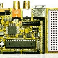
Chameleon-AVR Nurve Networks, Chameleon-AVR Datasheet - Page 163

Chameleon-AVR
Manufacturer Part Number
Chameleon-AVR
Description
MCU, MPU & DSP Development Tools AVR8 & PROPELLER DEV SYSTEM (SBC)
Manufacturer
Nurve Networks
Datasheet
1.CHAMELEON-AVR.pdf
(268 pages)
Specifications of Chameleon-AVR
Processor To Be Evaluated
AVR 328P
Data Bus Width
8 bit
Interface Type
USB, VGA, PS/2, I2C, ISP, SPI
Operating Supply Voltage
3.3 V, 5 V
Lead Free Status / RoHS Status
Lead free / RoHS Compliant
- Current page: 163 of 268
- Download datasheet (17Mb)
Description:
Example(s):
_________________________________________________________________________________________________
Function Prototype:
Description:
Programming
Finally, the function de-asserts the SPI_CS line, so any SPI device connected to the expansion interface will be
de-selected (if it’s using the SPI_CS line as the chip select, recall that you can use any I/O line you wish to
enable/disable a SPI slave, but bottom line is only a single SPI device better be on the MISO, MOSI, SCLK lines
at any time). Considering this, when you write code to control the SPI interface for example, before you make
calls to SPI write and read functions you will need to asserts the proper SPI_CS or appropriate SPI mux chip
selects SPI_CS0, SPI_CS1 to your SPI device while making sure all others are de-asserted. Returns 1 always.
int SPI_Set_Speed(unsigned char spi_rate);
Sidebar
Example 1: Initialize the SPI hardware and set speed to main clock divided by 128 (the slowest rate).
transmit and receive. Also, it’s important to recall with SPI whenever you send a byte you receive a byte
as well due to the circular buffering of output and input. You can review the function yourself for details,
but it sets the clock polarity and phase polarity to default mode 0 in both cases. Also, the single
parameter sent spi_rate is used to set the speed of the SPI interface in the “SPI Control Register 0”
speed control bits. The speed control bits control the “divisor” to the SPI hardware where the clock source
is the input frequency of the AVR 328P, thus, the control bits set the divisor allowing a number of possible
SPI clock rates. Writing to the SPI Control Register is straightforward, but some bit manipulation and
shifting is needed to obtain the desired results, thus the constants declared in the .H file below can be
used to set the clock speed:
SPI_Init(…) initializes the primary SPI hardware on the AVR 328 to master and sets it up so we can
SPI_Set_Speed(…) simply updates the speed of the SPI interface in real-time, allowing you to “throttle”
It is important to remember that the SPI’s built in CS line is not used to select anything.
Instead a pair of digital I/O lines are used as SPI “select” selection bits and are
multiplexed to select 1 of 4 devices named 0…3. The signals in the Chameleon design
are on Port C
#define SPI_CS0
#define SPI_CS1
To select device 0…3 you simply place 00
the FLASH, 10
are exported off the I/O headers to support other SPI devices you might connect. For
example, to select the Propeller chip you would use the following code:
// set CS to SPI select, select Prop SPI channel = 2
SPI_CS_PORT = (1 << SPI_CS1) | (0 << SPI_CS0);
And to de-select the Propeller and select device 0 (null device), you would use :
// set CS to SPI select channel 0 (null)
SPI_CS_PORT = (0 << SPI_CS1) | (0 << SPI_CS0);
b
(2) selects the Propeller as destination. The other two unused selectors
PC2
PC3
© 2009 NURVE NETWORKS LLC “Exploring the Chameleon AVR 8-Bit”
b
, 01
b
, 10
b
, 11
b
on these pins. 11
b
(3) selects
163
Related parts for Chameleon-AVR
Image
Part Number
Description
Manufacturer
Datasheet
Request
R

Part Number:
Description:
MCU, MPU & DSP Development Tools PIC24 & PROPELLER DEV SYSTEM (SBC)
Manufacturer:
Nurve Networks
Datasheet:

Part Number:
Description:
MCU, MPU & DSP Development Tools AVR8 VIDEO GAME DEV SYSTEM (SBC)
Manufacturer:
Nurve Networks

Part Number:
Description:
MCU, MPU & DSP Development Tools PIC24 VIDEO GAME DEV SYSTEM (SBC)
Manufacturer:
Nurve Networks


