Chameleon-AVR Nurve Networks, Chameleon-AVR Datasheet - Page 63
Chameleon-AVR
Manufacturer Part Number
Chameleon-AVR
Description
MCU, MPU & DSP Development Tools AVR8 & PROPELLER DEV SYSTEM (SBC)
Manufacturer
Nurve Networks
Datasheet
1.CHAMELEON-AVR.pdf
(268 pages)
Specifications of Chameleon-AVR
Processor To Be Evaluated
AVR 328P
Data Bus Width
8 bit
Interface Type
USB, VGA, PS/2, I2C, ISP, SPI
Operating Supply Voltage
3.3 V, 5 V
Lead Free Status / RoHS Status
Lead free / RoHS Compliant


© 2009 NURVE NETWORKS LLC “Exploring the Chameleon AVR 8-Bit”
12.2.5 Mouse Initialization
During the mouse power up both the DATA and CLOCK lines must be pulled HIGH and/or released/tristated by the host.
The mouse will then run its power up self test or BAT and start sending the results to the host. The host watches the
CLOCK and DATA lines to determine when this transmission occurs and should look for the code $AA (ok) followed by
$00 (mouse device ID). However, you can forgo this step if you like and just wait 1-2 seconds and “assume” the mouse
was plugged in properly. You do not have to respond to this code in other words. If you wish to Reset the mouse, you can
at any time send the command code $FF, and the mouse should respond with a $FA to acknowledge that everything
went well.
Once the mouse sends the $AA, $00 startup codes then the mouse enters its standard default mode as explained in the
sections above. The only thing we need to do to get the mouse sending packets is to tell the mouse to start reporting
movement. This is done by sending the command “Enable Data Reporting” ($F4), the mouse responds with $FA to
acknowledge the command worked and then will start streaming out 3-byte movement packets at the default rate of 100
samples/sec. This step is necessary, since on start up if the mouse simply started streaming data packets the host could
loose important data, thus the mouse “waits” to be told to start streaming the data and reporting the motion.
The movement data packets are formatted as shown in Table 12.5. You simply need to read these packets and send
them upstream to your application.
12.2.6 Reading Mouse Movement
Assuming that the mouse has been initialized and is in Streaming mode with Reporting mode enabled, then you simply
loop and read each 3-byte movement packet. As you read the first byte you use it to determine the state of the buttons as
well as any overflows with the counters. Then the next two bytes, the X and Y deltas should be added to running counters
(16-bit) that track the absolute position of the mouse cursor. That’s it!
Of course, this is only for your edification, the Propeller driver does all this for you, so all you have to do is send a simple
command from the AVR to the Propeller to read the keyboard or mouse.
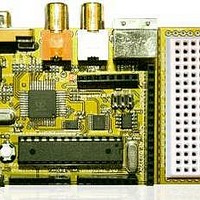
13.0 The I/O Headers
The I/O headers on the Chameleon AVR consist of a number signals that interface to both the AVR and Propeller chip.
The Propeller chip has its own 8-bit local I/O port located right under the composite video and PS/2 ports. The other
headers surrounding the Chameleon PCB interface mostly to the AVR chip. Let’s take a look at the PCB for a moment for
reference as shown in Figure 13.1.
Figure 13.1 – The Chameleon’s annotated I/O headers.
63
Related parts for Chameleon-AVR
Image
Part Number
Description
Manufacturer
Datasheet
Request
R

Part Number:
Description:
MCU, MPU & DSP Development Tools PIC24 & PROPELLER DEV SYSTEM (SBC)
Manufacturer:
Nurve Networks
Datasheet:

Part Number:
Description:
MCU, MPU & DSP Development Tools AVR8 VIDEO GAME DEV SYSTEM (SBC)
Manufacturer:
Nurve Networks

Part Number:
Description:
MCU, MPU & DSP Development Tools PIC24 VIDEO GAME DEV SYSTEM (SBC)
Manufacturer:
Nurve Networks