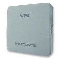
QB-MINI2-EE NEC, QB-MINI2-EE Datasheet - Page 116

QB-MINI2-EE
Manufacturer Part Number
QB-MINI2-EE
Description
EMULATOR, PROGRAMMER, MINICUBE2
Manufacturer
NEC
Type
Debug Emulatorr
Datasheet
1.QB-MINI2-EE.pdf
(169 pages)
Specifications of QB-MINI2-EE
Svhc
No SVHC (18-Jun-2010)
Mcu Supported Families
MINICUBE2
Silicon Family Name
V850, 78K0R, 78K0S
Ic Product Type
On-Chip Debug Emulator
Kit Contents
MINICUBE2, USB Cable, Target Cable, 78K0-OCD Board
Features
On-Chip Debugging, Flash Memory Programming,
- Current page: 116 of 169
- Download datasheet (6Mb)
5.2.5 Securing of user resources
116
implement each debug function.
program or using the compiler options.
• Securement of memory space
• Securement of serial interface for communication
The shaded portions in Figure 5-16 are the areas reserved for placing the debug monitor program, so user
programs cannot be allocated in these spaces.
The register settings, concerning the INTP pin used for communication between MINICUBE2 and the target
device, performed by the debug monitor program must not be changed.
The user must prepare the following to perform communication between MINICUBE2 and the target device and
Internal ROM space
Internal ROM space
304 bytes
304 bytes
2 bytes
2 bytes
2 bytes
2 bytes
Figure 5-16. Memory Spaces Where Debug Monitor Programs Are Allocated
CHAPTER 5
Internal ROM end address
Internal ROM end address
0x7E (for software break)
0x7E (for software break)
0x0A or 0x18 (INTP interrupt vector)
0x0A or 0x18 (INTP interrupt vector)
Refer to the descriptions on the following pages and set these items in the user
HOW TO USE MINICUBE2 WITH 78K0S MICROCONTROLLER
User’s Manual U18371EJ1V0UM
Internal RAM space
Internal RAM space
: Debug monitor program area
: Debug monitor program area
5 bytes
5 bytes
Internal RAM end address
Internal RAM end address
Stack area for debugging
Stack area for debugging
Related parts for QB-MINI2-EE
Image
Part Number
Description
Manufacturer
Datasheet
Request
R

Part Number:
Description:
16/8 bit single-chip microcomputer
Manufacturer:
NEC
Datasheet:

Part Number:
Description:
Dual audio power amp circuit
Manufacturer:
NEC
Datasheet:

Part Number:
Description:
Dual comparator
Manufacturer:
NEC
Datasheet:

Part Number:
Description:
MOS type composite field effect transistor
Manufacturer:
NEC
Datasheet:

Part Number:
Description:
50 V/100 mA FET array incorporating 2 N-ch MOSFETs
Manufacturer:
NEC
Datasheet:

Part Number:
Description:
6-pin small MM high-frequency double transistor
Manufacturer:
NEC
Datasheet:

Part Number:
Description:
6-pin small MM high-frequency double transistor
Manufacturer:
NEC
Datasheet:

Part Number:
Description:
6-pin small MM high-frequency double transistor
Manufacturer:
NEC
Datasheet:

Part Number:
Description:
6-pin small MM high-frequency double transistor
Manufacturer:
NEC
Datasheet:

Part Number:
Description:
Twin transistors equipped with different model chips(6P small MM)
Manufacturer:
NEC
Datasheet:

Part Number:
Description:
Bipolar analog integrated circuit
Manufacturer:
NEC
Datasheet:


