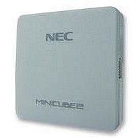
QB-MINI2-EE NEC, QB-MINI2-EE Datasheet - Page 89

QB-MINI2-EE
Manufacturer Part Number
QB-MINI2-EE
Description
EMULATOR, PROGRAMMER, MINICUBE2
Manufacturer
NEC
Type
Debug Emulatorr
Datasheet
1.QB-MINI2-EE.pdf
(169 pages)
Specifications of QB-MINI2-EE
Svhc
No SVHC (18-Jun-2010)
Mcu Supported Families
MINICUBE2
Silicon Family Name
V850, 78K0R, 78K0S
Ic Product Type
On-Chip Debug Emulator
Kit Contents
MINICUBE2, USB Cable, Target Cable, 78K0-OCD Board
Features
On-Chip Debugging, Flash Memory Programming,
- Current page: 89 of 169
- Download datasheet (6Mb)
<When interrupts are enabled (EI) (with an RRM generated while a user program main routine is running)>
(11) Period in which user program is stopped while pseudo real-time RAM monitor function is being
(12) Caution on mounting a clock on 78K0-OCD board
(13) Emulation of POC function
A
2 bytes
4 bytes
16 bytes
A (approx. 110 µ s)
B (approx. 1 ms)
C
RRM Function Sampling Range
processed
The sampling time can be set in the Extended Option dialog box.
The following shows the execution time, whereas the operating frequency = 5 MHz and PCC = 0.
When a clock is mounted on the 78K0-OCD board, power supply may not become the GND level even if the
power to the target system is shut down.
The POC function of the target device cannot be emulated. Make sure that the power to the target system is
not shut down during debugging
B
CHAPTER 4
: Pseudo real-time RAM monitor function processing in progress
: User program is running.
: User program is running (sampling time − A − (A + B) × sampling range).
(during a break: RRM data collection and RRM data transmission)
One cycle = Several tens ms to several hundreds ms
A
The A period occurs for the number of the RRM point bytes + 1.
Redraw Interval (sampling time)
HOW TO USE MINICUBE2 WITH 78K0 MICROCONTROLLER
B
110 + 110 × 2 = 330
110 + 110 × 4 = 440
110 + 110 × 16 = 1,870
User’s Manual U18371EJ1V0UM
Break Time per Cycle
A
µ
µ
s
s
B
µ
s
… A
110
110
110
Max. Interrupt Pending Time
µ
µ
µ
s
s
s
C
A
B
89
Related parts for QB-MINI2-EE
Image
Part Number
Description
Manufacturer
Datasheet
Request
R

Part Number:
Description:
16/8 bit single-chip microcomputer
Manufacturer:
NEC
Datasheet:

Part Number:
Description:
Dual audio power amp circuit
Manufacturer:
NEC
Datasheet:

Part Number:
Description:
Dual comparator
Manufacturer:
NEC
Datasheet:

Part Number:
Description:
MOS type composite field effect transistor
Manufacturer:
NEC
Datasheet:

Part Number:
Description:
50 V/100 mA FET array incorporating 2 N-ch MOSFETs
Manufacturer:
NEC
Datasheet:

Part Number:
Description:
6-pin small MM high-frequency double transistor
Manufacturer:
NEC
Datasheet:

Part Number:
Description:
6-pin small MM high-frequency double transistor
Manufacturer:
NEC
Datasheet:

Part Number:
Description:
6-pin small MM high-frequency double transistor
Manufacturer:
NEC
Datasheet:

Part Number:
Description:
6-pin small MM high-frequency double transistor
Manufacturer:
NEC
Datasheet:

Part Number:
Description:
Twin transistors equipped with different model chips(6P small MM)
Manufacturer:
NEC
Datasheet:

Part Number:
Description:
Bipolar analog integrated circuit
Manufacturer:
NEC
Datasheet:


