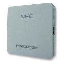
QB-MINI2-EE NEC, QB-MINI2-EE Datasheet - Page 7

QB-MINI2-EE
Manufacturer Part Number
QB-MINI2-EE
Description
EMULATOR, PROGRAMMER, MINICUBE2
Manufacturer
NEC
Type
Debug Emulatorr
Datasheet
1.QB-MINI2-EE.pdf
(169 pages)
Specifications of QB-MINI2-EE
Svhc
No SVHC (18-Jun-2010)
Mcu Supported Families
MINICUBE2
Silicon Family Name
V850, 78K0R, 78K0S
Ic Product Type
On-Chip Debug Emulator
Kit Contents
MINICUBE2, USB Cable, Target Cable, 78K0-OCD Board
Features
On-Chip Debugging, Flash Memory Programming,
CHAPTER 1 OVERVIEW........................................................................................................................... 10
CHAPTER 2 NAMES AND FUNCTIONS OF HARDWARE ..................................................................... 13
CHAPTER 3 HOW TO USE MINICUBE2 WITH V850 MICROCONTROLLER ........................................ 17
CHAPTER 4 HOW TO USE MINICUBE2 WITH 78K0 MICROCONTROLLER........................................ 50
1.1 Features ........................................................................................................................................ 10
1.2 Notes Before Using MINICUBE2 ................................................................................................. 11
1.3 Supported Devices....................................................................................................................... 11
1.4 Hardware Specifications ............................................................................................................. 12
2.1 Names of Supplied Hardware ..................................................................................................... 13
2.2 Part Names and Functions of MINICUBE2 ................................................................................ 14
2.3 Part Names and Functions of 78K0-OCD Board ....................................................................... 16
3.1 Target System Design ................................................................................................................. 18
3.2 On-Chip Debugging ..................................................................................................................... 27
3.3 Flash Programming ..................................................................................................................... 40
4.1 Target System Design ................................................................................................................. 51
4.2 On-Chip Debugging ..................................................................................................................... 71
3.1.1 Pin assignment ..............................................................................................................................19
3.1.2 Circuit connection examples ........................................................................................................20
3.1.3 Connection of reset pin.................................................................................................................23
3.1.4 Mounting connector onto target system .....................................................................................26
3.2.1 Debug functions.............................................................................................................................27
3.2.2 System configuration ....................................................................................................................28
3.2.3 System startup procedure ............................................................................................................29
3.2.4 System shutdown procedure........................................................................................................31
3.2.5 Securing of user resources and setting of security ID...............................................................32
3.2.6 Cautions on debugging.................................................................................................................38
3.3.1 Specifications of programming function .....................................................................................40
3.3.2 System configuration ....................................................................................................................40
3.3.3 System startup procedure ............................................................................................................41
3.3.4 Usage examples.............................................................................................................................43
3.3.5 System shutdown procedure........................................................................................................49
3.3.6 Cautions on flash programming...................................................................................................49
4.1.1 Pin assignment ..............................................................................................................................52
4.1.2 Circuit connection examples ........................................................................................................54
4.1.3 Connection of reset pin.................................................................................................................64
4.1.4 Cautions on target system design ...............................................................................................69
4.1.5 Mounting connector onto target system .....................................................................................70
4.2.1 Debug functions.............................................................................................................................71
4.2.2 System configuration ....................................................................................................................72
4.2.3 System startup procedure ............................................................................................................73
4.2.4 System shutdown procedure........................................................................................................76
User’s Manual U18371EJ1V0UM
CONTENTS
7


