CDB42L52 Cirrus Logic Inc, CDB42L52 Datasheet - Page 27
CDB42L52
Manufacturer Part Number
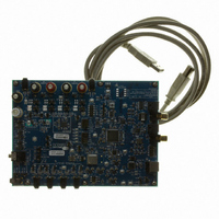
CDB42L52
Description
Eval Bd LP Codec W/Class D Spkr Driver
Manufacturer
Cirrus Logic Inc
Specifications of CDB42L52
Main Purpose
Audio, CODEC
Embedded
Yes, FPGA / CPLD
Utilized Ic / Part
CS42L52
Primary Attributes
4 Stereo Audio Inputs, Stereo Line and Speaker Outputs, S/PDIF Inputs and Outputs
Secondary Attributes
GUI, I2C, SPI, USB Interfaces
Description/function
Audio CODECs
Operating Supply Voltage
5 V
Product
Audio Modules
Lead Free Status / RoHS Status
Contains lead / RoHS non-compliant
For Use With/related Products
CS42L52
Lead Free Status / RoHS Status
Contains lead / RoHS non-compliant
Other names
598-1505


DS680F1
4.2.1
4.2.2
MIC Inputs
The input pins 21, 22, 23, and 24 accept stereo line-level or microphone signals. For microphone inputs,
either single-ended or differential configuration is allowed, providing programmable pre-amplification of
low-level signals. In the single-ended configuration, an internal MUX chooses one of two stereo sets (se-
lection is made independently on channels A and B). In the differential configuration, an internal voltage
follower cascaded with the pre-amplifier maintains high input impedance and provides noise rejection
above the MICxGAIN setting. The pre-amps are biased to VQ in both configurations.
Automatic Level Control (ALC)
When enabled, the ALC monitors the analog input signal after the digital attenuator, detects when peak
levels exceed the maximum (MAX) threshold settings, and responds by applying attenuation as neces-
sary to maintain the resulting level below the MAX threshold. To apply this attenuation, the ALC first low-
ers the PGA gain settings and then increases the digital attenuation levels. All attenuation is applied at a
programmable attack rate.
When input signal levels fall below the minimum (MIN) threshold, the ALC responds by removing any at-
tenuation that it has previously applied until all ALC-applied attenuation has been removed or until the
MAX threshold is again crossed. To remove this attenuation, the ALC first decreases the digital attenua-
tion levels and then increases the PGA gain. All attenuation is removed at a programmable release rate.
It should be noted that the ALC is applied independently to channels A and B with one exception: the input
signals on both channels A and B must be below the MIN threshold in order for the ALC attenuation to be
released on channel B.
Attack and release rates are affected by the ADC soft-ramp/zero-cross settings and sample rate, Fs. ALC
soft-ramp and zero-cross dependency may be independently enabled/disabled.
Recommended settings: Best level control may be realized with the fastest attack and slowest release
setting with soft ramp enabled in the control registers.
Notes:
1. When ALC x is enabled and the PGAxVOL[5:0] is set above 12 dB, the ADCxVOL[7:0] should not be
2. The maximum realized gain must be set in the PGAxVOL register. The ALC will only apply the gain
3. The ALC maintains the output signal between the MIN and MAX thresholds. As the input signal level
Referenced Control
MICxCFG ............................
PDN_MICx ..........................
MICxGAIN ...........................
Figure 6. Single-Ended MIC Configuration
MIC1A
MIC2A
MIC1B
MIC2B
set below 0 dB.
set in the PGAxVOL.
23
21
24
22
MICACFG=’0'b
MICBCFG=’0'b
MICASEL
MICBSEL
VQ
VQ
MICAGAIN[4:0]
MICBGAIN[4:0]
+
-
+
-
Register Location
“MICx Configuration” on page 55
“Power Down MICx” on page 43
“MICx Gain” on page 55
PDN_MICA=’0'b
PDN_MICB=’0'b
16..32 dB/
1 dB steps
16..32 dB/
1 dB steps
to summing
PGA A
to summing
PGA B
5/13/08
Figure 7. Differential MIC Configuration
MIC1-
MIC1+
MIC2-
MIC2+
Note: Output to PGA = (MIC
23
21
24
22
MICACFG=’1'b
MICBCFG=’1'b
+
+
-
-
+
MICAGAIN[4:0]
MICBGAIN[4:0]
- MIC
+
-
+
-
-
)*gain + MIC
PDN_MICA=’0'b
PDN_MICB=’0'b
16..32 dB/
1 dB steps
16..32 dB/
1 dB steps
-
CS42L52
to summing
PGA A
to summing
PGA B
27
Related parts for CDB42L52
Image
Part Number
Description
Manufacturer
Datasheet
Request
R

Part Number:
Description:
Development Kit
Manufacturer:
Cirrus Logic Inc
Datasheet:
Part Number:
Description:
Development Kit
Manufacturer:
Cirrus Logic Inc
Datasheet:


Part Number:
Description:
High-efficiency PFC + Fluorescent Lamp Driver Reference Design
Manufacturer:
Cirrus Logic Inc
Datasheet:
Part Number:
Description:
Development Kit
Manufacturer:
Cirrus Logic Inc
Datasheet:
Part Number:
Description:
Development Kit
Manufacturer:
Cirrus Logic Inc
Datasheet:

Part Number:
Description:
Development Kit
Manufacturer:
Cirrus Logic Inc
Datasheet:
Part Number:
Description:
Development Kit
Manufacturer:
Cirrus Logic Inc
Datasheet:
Part Number:
Description:
Development Kit
Manufacturer:
Cirrus Logic Inc
Datasheet:
Part Number:
Description:
Development Kit
Manufacturer:
Cirrus Logic Inc
Datasheet:

Part Number:
Description:
EVALUATION BOARD FOR CS8427
Manufacturer:
Cirrus Logic Inc
Datasheet:

Part Number:
Description:
BOARD EVAL FOR CS8416 RCVR
Manufacturer:
Cirrus Logic Inc
Datasheet:

Part Number:
Description:
EVALUATION BOARD FOR CS8420
Manufacturer:
Cirrus Logic Inc
Datasheet:

Part Number:
Description:
KIT DEVELOPMENT EP9315 ARM9
Manufacturer:
Cirrus Logic Inc
Datasheet:

Part Number:
Description:
KIT DEVELOPMENT EP9302 ARM9
Manufacturer:
Cirrus Logic Inc
Datasheet: