C8051F411-GMR Silicon Laboratories Inc, C8051F411-GMR Datasheet - Page 142
C8051F411-GMR
Manufacturer Part Number
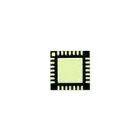
C8051F411-GMR
Description
Microcontrollers (MCU) 50 MIPS 32KB 12ADC RTCLOCK 28 PIN MCU
Manufacturer
Silicon Laboratories Inc
Datasheet
1.C8051F410DK.pdf
(270 pages)
Specifications of C8051F411-GMR
Processor Series
C8051F4x
Core
8051
Data Bus Width
8 bit
Program Memory Type
Flash
Program Memory Size
32 KB
Data Ram Size
2.25 KB
Interface Type
I2C, SMBus, SPI, UART
Maximum Clock Frequency
50 MHz
Number Of Programmable I/os
20
Number Of Timers
4
Maximum Operating Temperature
+ 85 C
Mounting Style
SMD/SMT
Package / Case
QFN
3rd Party Development Tools
PK51, CA51, A51, ULINK2
Development Tools By Supplier
C8051F410DK
Minimum Operating Temperature
- 40 C
On-chip Adc
12 bit, 20 Channel
On-chip Dac
12 bit, 2 Channel
Package
28QFN EP
Device Core
8051
Family Name
C8051F41x
Maximum Speed
50 MHz
Ram Size
2.25 KB
Operating Supply Voltage
1.8|2.5|3.3|5 V
Operating Temperature
-40 to 85 °C
Lead Free Status / Rohs Status
Details
Available stocks
Company
Part Number
Manufacturer
Quantity
Price
Company:

Part Number:
C8051F411-GMR
Manufacturer:
SiliconL
Quantity:
3 000
Part Number:
C8051F411-GMR
Manufacturer:
SILICON LABS/芯科
Quantity:
20 000


C8051F410/1/2/3
16.5. Flash Read Timing
On reset, the C8051F41x Flash read timing is configured for operation with system clocks up to 25 MHz. If
the system clock will not be increased above 25 MHz, then the Flash timing registers may be left at their
reset value.
For every Flash read or fetch, the system provides an internal Flash read strobe to the Flash memory. The
Flash read strobe lasts for one or two system clock cycles, based on FLRT (FLSCL.4). If the system
clock is greater than 25 MHz, the FLRT bit must be set to logic 1 , otherwise data read or fetched from
Flash may not represent the actual contents of Flash.
When the Flash read strobe is asserted, Flash memory is active. When it is de-asserted, Flash memory is
in a low power state. The Flash read strobe does not need to be asserted for longer than 80 ns in order for
Flash reads and fetches to be reliable. For system clocks greater than 12.5 MHz (but less than 25 MHz),
the Flash read strobe width is limited by the system clock period. For system clocks less than 12.5 MHz,
the Flash read strobe is limited by a programmable one shot with a default period of 80 ns (1/12.5 MHz).
This is a power saving feature that is very beneficial for very slow system clocks (e.g. 32.768 kHz where
the system clock period is greater than 30,000 ns).
For additional power savings, the one shot can be programmed to values less than 80 ns. The one shot
can be trimmed according the equation in the ONESHOT register description in Figure 16.4. The one shot
period must not be programmed less than the minimum read cycle time specified in Table 16.2.
The recommended procedure for updating FLRT or the ONESHOT period is:
142
Bits7–5: RESERVED. Read = 000b. Must Write 000b.
Bit 4:
Bits3–0: RESERVED. Must Write 0000b.
Reserved Reserved Reserved
R/W
Bit7
Step 1. Select SYSCLK to 25 MHz or less.
Step 2. Disable the prefetch engine (PFEN = ‘0’ in PFE0CN register).
Step 3. Clear FLRT to ‘0’ (FLSCL register).
Step 4. Set the ONESHOT period bits.
Step 5. Set FLRT to ‘1’ if SYSCLK > 25 MHz.
Step 6. Enable the prefetch engine (PFEN = ‘1’ in PFE0CN register).
FLRT: Flash Read Time Control.
This bit should be programmed to the smallest allowed value, according to the system clock
speed.
0: SYSCLK < 25 MHz (Flash read strobe is one system clock).
1: SYSCLK > 25 MHz (Flash read strobe is two system clocks).
R/W
Bit6
SFR Definition 16.3. FLSCL: Flash Scale
R/W
Bit5
FLRT
R/W
Bit4
Reserved Reserved Reserved Reserved 00000011
Rev. 1.1
R/W
Bit3
R/W
Bit2
R/W
Bit1
SFR Address:
R/W
Bit0
0xB6
Reset Value
Related parts for C8051F411-GMR
Image
Part Number
Description
Manufacturer
Datasheet
Request
R

Part Number:
Description:
SMD/C°/SINGLE-ENDED OUTPUT SILICON OSCILLATOR
Manufacturer:
Silicon Laboratories Inc
Part Number:
Description:
Manufacturer:
Silicon Laboratories Inc
Datasheet:
Part Number:
Description:
N/A N/A/SI4010 AES KEYFOB DEMO WITH LCD RX
Manufacturer:
Silicon Laboratories Inc
Datasheet:
Part Number:
Description:
N/A N/A/SI4010 SIMPLIFIED KEY FOB DEMO WITH LED RX
Manufacturer:
Silicon Laboratories Inc
Datasheet:
Part Number:
Description:
N/A/-40 TO 85 OC/EZLINK MODULE; F930/4432 HIGH BAND (REV E/B1)
Manufacturer:
Silicon Laboratories Inc
Part Number:
Description:
EZLink Module; F930/4432 Low Band (rev e/B1)
Manufacturer:
Silicon Laboratories Inc
Part Number:
Description:
I°/4460 10 DBM RADIO TEST CARD 434 MHZ
Manufacturer:
Silicon Laboratories Inc
Part Number:
Description:
I°/4461 14 DBM RADIO TEST CARD 868 MHZ
Manufacturer:
Silicon Laboratories Inc
Part Number:
Description:
I°/4463 20 DBM RFSWITCH RADIO TEST CARD 460 MHZ
Manufacturer:
Silicon Laboratories Inc
Part Number:
Description:
I°/4463 20 DBM RADIO TEST CARD 868 MHZ
Manufacturer:
Silicon Laboratories Inc
Part Number:
Description:
I°/4463 27 DBM RADIO TEST CARD 868 MHZ
Manufacturer:
Silicon Laboratories Inc
Part Number:
Description:
I°/4463 SKYWORKS 30 DBM RADIO TEST CARD 915 MHZ
Manufacturer:
Silicon Laboratories Inc
Part Number:
Description:
N/A N/A/-40 TO 85 OC/4463 RFMD 30 DBM RADIO TEST CARD 915 MHZ
Manufacturer:
Silicon Laboratories Inc
Part Number:
Description:
I°/4463 20 DBM RADIO TEST CARD 169 MHZ
Manufacturer:
Silicon Laboratories Inc