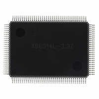
X98014L128-3.3-Z Intersil, X98014L128-3.3-Z Datasheet - Page 14

X98014L128-3.3-Z
Manufacturer Part Number
X98014L128-3.3-Z
Description
IC VIDEO DIGITIZER TRPL 128MQFP
Manufacturer
Intersil
Type
Video Digitizer, 3-Channel AFEr
Datasheet
1.X98014L128-3.3-Z.pdf
(29 pages)
Specifications of X98014L128-3.3-Z
Applications
LCD TV/Monitor
Mounting Type
Surface Mount
Package / Case
128-MQFP, 128-PQFP
Rohs Compliant
Yes
Lead Free Status / RoHS Status
Lead free / RoHS Compliant
Available stocks
Company
Part Number
Manufacturer
Quantity
Price
Company:
Part Number:
X98014L128-3.3-Z
Manufacturer:
Intersil
Quantity:
3
Company:
Part Number:
X98014L128-3.3-Z
Manufacturer:
Intersil
Quantity:
1 900
Part Number:
X98014L128-3.3-Z
Manufacturer:
INTERSIL
Quantity:
20 000
Register Listing
0x17
0x18
0x19
0x1A
ADDRESS
ABLC™ Configuration (0x40)
Output Format (0x00)
HSOUT Width (0x10)
Output Signal Disable (0x00)
REGISTER (DEFAULT VALUE)
(Continued)
14
0
1
3:2
6:4
7
0
1
2
3
4
5
6
7
7:0
0
1
2
3
4
5
6
7
BIT(s)
ABLC™ disable
Reserved
ABLC™ pixel width
ABLC™ bandwidth
Reserved
Bus Width
Interleaving
(48 bit mode only)
Bus Swap
(48 bit mode only)
Reserved
422
(24 bit mode only)
DATACLK
Polarity
VSOUT Polarity
HSOUT Polarity
HSOUT Width
Three-state R
Three-state R
Three-state G
Three-state G
Three-state B
Three-state B
Three-state
DATACLK
Three-state
DATACLK
FUNCTION NAME
X98014
P
S
P
S
P
S
[7:0]
[7:0]
[7:0]
[7:0]
[7:0]
[7:0]
0: ABLC™ enabled (default)
1: ABLC™ disabled
Set to 0.
Number of black pixels averaged every line for ABLC™
function
00: 16 pixels [default]
01: 32 pixels
10: 64 pixels
11: 128 pixels
ABLC™ Time constant (lines) = 2
000 = 32 lines
100 = 512 lines (default)
111 = 4096 lines
Set to 0.
0: 24 bits: Data output on R
driven low (default)
1: 48 bits: Data output on R
0: No interleaving: data changes on same edge of DATACLK
(default)
1: Interleaved: Secondary databus data changes on
opposite edge of DATACLK from primary databus
0: First data byte after trailing edge of HSOUT appears on
R
1: First data byte after trailing edge of HSOUT appears on
R
Set to 0.
0: Data is formatted as 4:4:4 (RGB, default)
1: Data is decimated to 4:2:2 (YUV), blue channel is driven
low
0: HS
DATACLK (default)
1: HS
DATACLK
0: Active High (default)
1: Active Low
0: Active High (default)
1: Active Low
HSOUT width, in pixels. Minimum value is 0x01 for 24 bit
modes, 0x02 for 48 bit modes.
0 = Output byte enabled
1 = Output byte three-stated
These bits override all other I/O settings
Output data pins have 58kΩ pulldown resistors to GND
0 = DATACLK enabled
1 = DATACLK three-stated
0 = DATACLK enabled
1 = DATACLK three-stated
P
S
, G
, G
OUT
P
OUT
S
, B
, B
P
, VS
, VS
S
(default)
(primary and secondary busses are reversed)
OUT
OUT
, and Pixel Data change on falling edge of
, and Pixel Data change on rising edge of
DESCRIPTION
P
P
, G
, G
P
P
, B
, B
(5+[6:4])
P
P
only; R
, R
S
, G
S
S
, G
, B
S
S
, B
March 8, 2006
S
FN8217.3
are all
D
.


