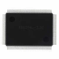
X98014L128-3.3-Z Intersil, X98014L128-3.3-Z Datasheet - Page 22

X98014L128-3.3-Z
Manufacturer Part Number
X98014L128-3.3-Z
Description
IC VIDEO DIGITIZER TRPL 128MQFP
Manufacturer
Intersil
Type
Video Digitizer, 3-Channel AFEr
Datasheet
1.X98014L128-3.3-Z.pdf
(29 pages)
Specifications of X98014L128-3.3-Z
Applications
LCD TV/Monitor
Mounting Type
Surface Mount
Package / Case
128-MQFP, 128-PQFP
Rohs Compliant
Yes
Lead Free Status / RoHS Status
Lead free / RoHS Compliant
Available stocks
Company
Part Number
Manufacturer
Quantity
Price
Company:
Part Number:
X98014L128-3.3-Z
Manufacturer:
Intersil
Quantity:
3
Company:
Part Number:
X98014L128-3.3-Z
Manufacturer:
Intersil
Quantity:
1 900
Part Number:
X98014L128-3.3-Z
Manufacturer:
INTERSIL
Quantity:
20 000
HSYNC
HSYNC
incoming HSYNC
channel, with the incoming signal’s period, polarity, and
width to aid in mode detection. HSYNC
format as the incoming sync signal: either horizontal or
composite sync. If a SOG input is selected, HSYNC
output the entire SOG signal, including the VSYNC portion,
pre-/post-equalization pulses if present, and Macrovision
pulses if present. HSYNC
X98014 is in power down mode. HSYNC
used for mode detection.
VSYNC
VSYNC
incoming VSYNC
original VSYNC period, polarity, and width to aid in mode
detection. If a SOG input is selected, this signal will output
the VSYNC signal extracted by the X98014’s sync slicer.
Extracted VSYNC will be the width of the embedded VSYNC
pulse plus pre- and post-equalization pulses (if present).
Macrovision pulses from an NTSC DVD source will lengthen
the width of the VSYNC pulse. Macrovision pulses from
other sources (PAL DVD or videotape) may appear as a
second VSYNC pulse encompassing the width of the
Macrovision. See the Macrovision section for more
information. VSYNC
function) remains active in power down mode. VSYNC
is generally used for mode detection, start of field detection,
and even/odd field detection.
HS
HS
synchronized to the output DATACLK and the digital pixel
data on the output databus. Its trailing edge is aligned with
pixel 0. Its width, in units of pixels, is determined by register
0x19, and its polarity is determined by register 0x18[7]. As
the width is increased, the trailing edge stays aligned with
pixel 0, while the leading edge is moved backwards in time
relative to pixel 0. HS
start of a new line of pixels.
The HSOUT Width register (0x19) controls the width of the
HS
period times the value in this register. In the 48 bit output
mode (register 0x18[0] = 1), or the YUV input mode (register
0x05[2] = 1), the HS
(1 DATACLK) increments (see Table 7).
OUT
OUT
OUT
OUT
OUT
is generated by the X98014’s control logic and is
pulse. The pulse width is nominally 1 pixel clock
OUT
OUT
is an unmodified, buffered version of the
is an unmodified, buffered version of the
IN
IN
OUT
signal of the selected channel, with the
or SOG
OUT
OUT
width is incremented in 2 pixel clock
(including the sync separator
OUT
is used by the scaler to signal the
IN
22
remains active when the
signal of the selected
OUT
OUT
will be the same
is generally
OUT
OUT
will
X98014
VS
VS
synchronized to the output DATACLK and the digital pixel
data on the output databus. Its leading and trailing edges are
aligned with pixel 7 (8 pixels after HSYNC trailing edge). Its
width, in units of lines, is equal to the width of the incoming
VSYNC (see the VSYNC
determined by register 0x18[6]. This output is not needed in
most applications.
Macrovision
The X98014 will synchronize to and digitize Macrovision-
encoded YUV video if the source is an NTSC DVD.
Macrovision from PAL DVD, or from all video tape sources,
is incompatible with the sync slicer, requiring that the
Macrovision pulses either be stripped from the video prior to
the SOG
and applied to the CLKINV pin that will coast the X98014’s
PLL during the VSYNC and Macrovision period.
Standby Mode
The X98014 can be placed into a low power standby mode
by writing a 0x0F to register 0x1B, powering down the triple
ADCs, the DPLL, and most of the internal clocks.
To allow input monitoring and mode detection during power
down, the following blocks remain active:
• Serial interface (including the crystal oscillator) to enable
• Activity and polarity detect functions (registers 0x01 and
• The HSYNC
0x19 VALUE
register read/write activity
0x02)
detection)
REGISTER
OUT
OUT
0
1
2
3
4
5
6
7
is generated by the X98014’s control logic and is
IN
input, or an external COAST signal be generated
OUT
24 BIT MODE,
TABLE 7. HS
and VSYNC
RGB
0
1
2
3
4
5
6
7
HS
OUT
OUT
WIDTH (PIXEL CLOCKS)
description). Its polarity is
OUT
24 BIT MODE,
OUT
WIDTH
YUV
pins (for mode
1
1
3
3
5
5
7
7
ALL 48 BIT
MODES
March 8, 2006
0
0
2
2
4
4
6
6
FN8217.3


