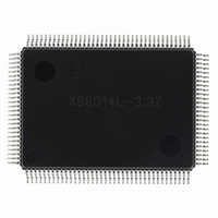
X98014L128-3.3-Z Intersil, X98014L128-3.3-Z Datasheet - Page 15

X98014L128-3.3-Z
Manufacturer Part Number
X98014L128-3.3-Z
Description
IC VIDEO DIGITIZER TRPL 128MQFP
Manufacturer
Intersil
Type
Video Digitizer, 3-Channel AFEr
Datasheet
1.X98014L128-3.3-Z.pdf
(29 pages)
Specifications of X98014L128-3.3-Z
Applications
LCD TV/Monitor
Mounting Type
Surface Mount
Package / Case
128-MQFP, 128-PQFP
Rohs Compliant
Yes
Lead Free Status / RoHS Status
Lead free / RoHS Compliant
Available stocks
Company
Part Number
Manufacturer
Quantity
Price
Company:
Part Number:
X98014L128-3.3-Z
Manufacturer:
Intersil
Quantity:
3
Company:
Part Number:
X98014L128-3.3-Z
Manufacturer:
Intersil
Quantity:
1 900
Part Number:
X98014L128-3.3-Z
Manufacturer:
INTERSIL
Quantity:
20 000
Register Listing
Technical Highlights
The X98014 provides all the features of traditional triple
channel video AFEs, but adds several next-generation
enhancements, bringing performance and ease of use to
new levels.
DPLL
All video AFEs must phase lock to an HSYNC signal,
supplied either directly or embedded in the video stream
(Sync On Green). Historically this function has been
implemented as a traditional analog PLL. At SXGA and
lower resolutions, an analog PLL solution has proven
adequate, if somewhat troublesome (due to the need to
adjust charge pump currents, VCO ranges and other
parameters to find the optimum trade-off for a wide range of
pixel rates).
As display resolutions and refresh rates have increased,
however, the pixel period has decreased. An XGA pixel at a
60Hz refresh rate has 15.4ns to change and settle to its new
value. But at UXGA 75Hz, the pixel period is 4.9ns. Most
consumer graphics cards spend most of that time slewing to
the new pixel value. The pixel may settle to its final value
with 1ns or less before it begins slewing to the next pixel. In
many cases it never settles at all. So precision, low-jitter
sampling is a fundamental requirement at these speeds, and
a difficult one for an analog PLL to meet.
The X98014's DPLL has less than 250ps of jitter, peak to
peak, and independent of the pixel rate. The DPLL
0x1B
0x1C
0x23
ADDRESS
Power Control (0x00)
Reserved (0x47)
DC Restore Clamp (0x08)
REGISTER (DEFAULT VALUE)
(Continued)
15
0
1
2
3
7:4
7:0
3:0
6:4
7
BIT(s)
Red
Power Down
Green
Power Down
Blue
Power Down
PLL
Power Down
Reserved
Reserved
Reserved
DC Restore Clamp
Impedance
Reserved
FUNCTION NAME
X98014
generates 64 phase steps per pixel (vs. the industry
standard 32), for fine, accurate positioning of the sampling
point. The crystal-locked NCO inside the DPLL completely
eliminates drift due to charge pump leakage, so there is
inherently no frequency or phase change across a line. An
intelligent all-digital loop filter/controller eliminates the need
for the user to have to program or change anything (except
for the number of pixels) to lock over a range from interlaced
video (10MHz or higher) to SXGA 75Hz (140MHz).
The DPLL eliminates much of the performance limitations
and complexity associated with noise-free digitization of high
speed signals.
Automatic Black Level Compensation (ABLC™)
and Gain Control
Traditional video AFEs have an offset DAC prior to the ADC,
to both correct for offsets on the incoming video signals and
add/subtract an offset for user “brightness control”. This
solution is adequate, but it places significant requirements
on the system's firmware, which must execute a loop that
detects the black portion of the signal and then servos the
offset DACs until that offset is nulled (or produces the
desired ADC output code). Once this has been
accomplished, the offset (both the offset in the AFE and the
offset of the video card generating the signal) is subject to
drift - the temperature inside a monitor or projector can
easily change 50°C between power-on/offset calibration on a
cold morning and the temperature reached once the monitor
and the monitor's environment have reached steady state.
0 = Red ADC operational (default)
1 = Red ADC powered down
0 = Green ADC operational (default)
1 = Green ADC powered down
0 = Blue ADC operational (default)
1 = Blue ADC powered down
0 = PLL operational (default)
1 = PLL powered down
Set to 0
Set to 0x49 for best performance with NTSC and PAL video
Set to 1000
DC Restore clamp's ON resistance.
Shared for all three channels
0: Infinite (clamp disconnected) (default)
1: 1600Ω
2: 800Ω
3: 533Ω
4: 400Ω
5: 320Ω
6: 267Ω
7: 228Ω
Set to 0
DESCRIPTION
March 8, 2006
FN8217.3


