X98014L128-3.3-Z Intersil, X98014L128-3.3-Z Datasheet - Page 21

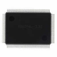
X98014L128-3.3-Z
Manufacturer Part Number
X98014L128-3.3-Z
Description
IC VIDEO DIGITIZER TRPL 128MQFP
Manufacturer
Intersil
Type
Video Digitizer, 3-Channel AFEr
Datasheet
1.X98014L128-3.3-Z.pdf
(29 pages)
Specifications of X98014L128-3.3-Z
Applications
LCD TV/Monitor
Mounting Type
Surface Mount
Package / Case
128-MQFP, 128-PQFP
Rohs Compliant
Yes
Lead Free Status / RoHS Status
Lead free / RoHS Compliant
Available stocks
Company
Part Number
Manufacturer
Quantity
Price
Company:
Part Number:
X98014L128-3.3-Z
Manufacturer:
Intersil
Quantity:
3
Company:
Part Number:
X98014L128-3.3-Z
Manufacturer:
Intersil
Quantity:
1 900
Part Number:
X98014L128-3.3-Z
Manufacturer:
INTERSIL
Quantity:
20 000
HSYNC and VSYNC Activity Detect
Activity on these bits always indicates valid sync pulses, so
they should have the highest priority and be used even if the
SOG activity bit is also set.
SOG Activity Detect
The SOG activity detect bit monitors the output of the SOG
slicer, looking for 64 consecutive pulses with the same
period and duty cycle. If there is no signal on the Green
(or Y) channel, the SOG slicer will clamp the video to a DC
level and will reject any sporadic noise. There should be no
false positive SOG detects if there is no video on Green
(or Y).
If there is video on Green (or Y) with no valid SOG signal,
the SOG activity detect bit may sometimes report false
positives (it will detect SOG when no SOG is actually
present). This is due to the presence of video with a
repetitive pattern that creates a waveform similar to SOG.
For example, the desktop of a PC operating system is black
during the front porch, horizontal sync, and back porch, then
increases to a larger value for the visible portion of the
screen. This creates a repetitive video waveform very
similar to SOG that may falsely trigger the SOG Activity
detect bit. However, in these cases where there is active
video without SOG, the SYNC information will be provided
either as separate H and V sync on HSYNC
VSYNC
VSYNC
SOG Active bit should only be considered valid if HSYNC
Activity Detect = 0. Note: Some pattern generators can
output HSYNC and SOG simultaneously, in which case both
the HSYNC and the SOG activity bits will be set, and valid.
Even in this case, however, the monitor should still choose
HSYNC over SOG.
TriLevel Sync Detect
Unlike SOG detect, the TriLevel Sync detect function does
not check for 64 consecutive trilevel pulses in a row, and is
therefore less robust than the SOG detect function. It will
report false positives for SOG-less video for the same
reasons the SOG activity detect does, and should therefore
be qualified with both HSYNC and SOG. TriLevel Sync
DETECT
HSYNC
1
1
0
0
0
IN
IN
, or composite sync on HSYNC
should therefore be used to qualify SOG. The
DETECT
VSYNC
1
0
0
0
0
DETECT
21
SOG
X
X
1
1
0
TRILEVEL
DETECT
IN
X
X
X
TABLE 6. SYNC SOURCE DETECTION TABLE
0
1
. HSYNC
IN
and
Sync is on HSYNC and VSYNC
Sync is composite sync on HSYNC. Set Input configuration register to CSYNC on HSYNC
and confirm that CSYNC detect bit is set.
Sync is composite sync on SOG. It is possible that trilevel sync is present but amplitude
is too low to set trilevel detect bit. Use video mode table to determine if this video mode is
likely to have trilevel sync, and set clamp start, width values appropriately if it is.
Sync is composite sync on SOG. Sync is likely to be trilevel.
No valid sync sources on any input.
IN
and
X98014
Detect should only be considered valid if HSYNC Activity
Detect = 0 and SOG Activity Detect = 1.
If there is a SOG signal, the TriLevel Detect bit will operate
correctly for standard trilevel sync levels (600mVp-p). In
some real-world situations, the peak-to-peak sync amplitude
may be significantly smaller, sometimes 300mVp-p or less.
In these cases the sync slicer will continue to operate
correctly, but the TriLevel Detect bit may not be set. Trilevel
detection accuracy can be enhanced by polling the trilevel
bit multiple times. If HSYNC is inactive, SOG is present, and
the TriLevel Sync Detect bit is read as a 1, there is a high
likelihood there is trilevel sync.
CSYNC Present
If a composite sync source (either CSYNC on HSYNC or
SOG) is selected through bits 3 and 4 of register 0x05, the
CSYNC Present bit in register 0x01 should be set. CSYNC
Present detects the presence of a low frequency, repetitive
signal inside HSYNC, which indicates a VSYNC signal. The
CSYNC Present bit should be used to confirm that the signal
being received is a reliable composite sync source.
SYNC Output Signals
The X98014 has 2 pairs of HSYNC and VSYNC output
signals, HSYNC
VS
HSYNC
incoming sync signals; no synchronization is done. These
signals should be used for mode detection.
HS
and are synchronized to the output DATACLK and the digital
pixel data on the output databus. HS
the start of a new line of digital data. VS
most applications.
Both HSYNC
separator function) remain active in power down mode. This
allows them to be used in conjunction with the Sync Status
registers to detect valid video without powering up the
X98014.
OUT
OUT
.
OUT
and VS
and VSYNC
OUT
OUT
OUT
RESULT
and VSYNC
are generated by the X98014’s logic
and VSYNC
OUT
are buffered versions of the
OUT
OUT
(including the sync
OUT
, and HS
OUT
is used to signal
is not needed in
OUT
March 8, 2006
and
FN8217.3


