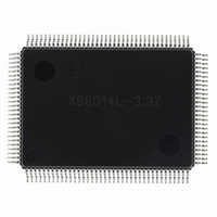
X98014L128-3.3-Z Intersil, X98014L128-3.3-Z Datasheet - Page 3

X98014L128-3.3-Z
Manufacturer Part Number
X98014L128-3.3-Z
Description
IC VIDEO DIGITIZER TRPL 128MQFP
Manufacturer
Intersil
Type
Video Digitizer, 3-Channel AFEr
Datasheet
1.X98014L128-3.3-Z.pdf
(29 pages)
Specifications of X98014L128-3.3-Z
Applications
LCD TV/Monitor
Mounting Type
Surface Mount
Package / Case
128-MQFP, 128-PQFP
Rohs Compliant
Yes
Lead Free Status / RoHS Status
Lead free / RoHS Compliant
Available stocks
Company
Part Number
Manufacturer
Quantity
Price
Company:
Part Number:
X98014L128-3.3-Z
Manufacturer:
Intersil
Quantity:
3
Company:
Part Number:
X98014L128-3.3-Z
Manufacturer:
Intersil
Quantity:
1 900
Part Number:
X98014L128-3.3-Z
Manufacturer:
INTERSIL
Quantity:
20 000
Absolute Maximum Ratings
Voltage on V
Voltage on any analog input pin
Voltage on any digital input pin
Current into any output pin . . . . . . . . . . . . . . . . . . . . . . . . . . . . . . ±20mA
Operating Temperature range . . . . . . . . . . . . . . . . . . . . . 0°C to +70°C
Junction Temperature . . . . . . . . . . . . . . . . . . . . . . . . . . . . . . +125°C
Storage Temperature. . . . . . . . . . . . . . . . . . . . . . . .-65°C to +150°C
CAUTION: Stresses above those listed under “Absolute Maximum Ratings” may cause permanent damage to the device. This is a stress rating only; functional
operation of the device (at these or any other conditions above those listed in the operational sections of this specification) is not implied. Exposure to absolute
maximum rating conditions for extended periods may affect device reliability.
T
Electrical Specifications
FULL CHANNEL CHARACTERISTICS
ANALOG VIDEO INPUT CHARACTERISTICS (R
INPUT CHARACTERISTICS (SOG
INPUT CHARACTERISTICS (HSYNC
(referenced to GND
(referenced to GND
(referenced to GND
SYMBOL
V
V
DNL
IH
IH
INL
R
IN
/V
/V
IL
IL
A
ADC Resolution
Missing Codes
Conversion Rate
Differential Non-Linearity
Integral Non-Linearity
Gain Adjustment Range
Gain Adjustment Resolution
Gain Matching Between Channels
Full Channel Offset Error, ABLC™ enabled ADC LSBs, over time and temperature
Offset Adjustment Range, ABLC™
enabled or disabled
Overvoltage Recovery Time
Input Range
Input Bias Current
Input Capacitance
Full Power Bandwidth
Input Threshold Voltage
Hysteresis
Input capacitance
Input Threshold Voltage
Hysteresis
Input impedance
, V
D
, or V
A
A
D
=GND
) . . . . . . . . . . . . . . . . . . . . . . . . . . -0.3V to V
) . . . . . . . . . . . . . . . . . . . . . . . -0.3V to +6.0V
X
PARAMETER
D
=GND
3
Specifications apply for V
unless otherwise noted
X
IN
) . . . . . . . . . . . . . . . . . . . 4.0V
1, SOG
IN
1, HSYNC
IN
2)
IN
IN
1, G
2)
Per Channel
IN
DC restore clamp off
Guaranteed monotonic
Percent of full scale
ADC LSBs (see ABLC™ applications
information section)
For 150% overrange, maximum bandwidth
setting
Programmable
Programmable - See Register Listing for
Details
Centered around threshold voltage
Programmable - See Register Listing for
Details
Centered around threshold voltage
1, B
A
= V
IN
1, R
A
D
X98014
= V
IN
X
2, G
COMMENT
= 3.3V, pixel rate = 140MHz, f
IN
2, B
Recommended Operating Conditions
Temperature (Commercial) . . . . . . . . . . . . . . . . . . . . . 0°C to +70°C
Supply Voltage. . . . . . . . . . . . . . . . . . . . . . . . . V
IN
2)
XTAL
0.35
MIN
10
8
= 25MHz, T
0.4 to 3.2
±0.125
±0.01
±127
TYP
±0.5
±1.1
-0.3
780
0 to
240
0.7
1.2
±6
±1
40
8
5
5
5
A
= 25°C,
A
±2.75
None
MAX
+1.0
±0.5
-0.9
140
1.4
±1
= V
D
= V
March 8, 2006
X
UNIT
MHz
V
MHz
FN8217.3
LSB
LSB
LSB
LSB
Bits
Bits
mV
mV
dB
µA
kΩ
ns
pF
pF
= 3.3V
%
P-P
V
V


