X98014L128-3.3-Z Intersil, X98014L128-3.3-Z Datasheet - Page 24

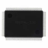
X98014L128-3.3-Z
Manufacturer Part Number
X98014L128-3.3-Z
Description
IC VIDEO DIGITIZER TRPL 128MQFP
Manufacturer
Intersil
Type
Video Digitizer, 3-Channel AFEr
Datasheet
1.X98014L128-3.3-Z.pdf
(29 pages)
Specifications of X98014L128-3.3-Z
Applications
LCD TV/Monitor
Mounting Type
Surface Mount
Package / Case
128-MQFP, 128-PQFP
Rohs Compliant
Yes
Lead Free Status / RoHS Status
Lead free / RoHS Compliant
Available stocks
Company
Part Number
Manufacturer
Quantity
Price
Company:
Part Number:
X98014L128-3.3-Z
Manufacturer:
Intersil
Quantity:
3
Company:
Part Number:
X98014L128-3.3-Z
Manufacturer:
Intersil
Quantity:
1 900
Part Number:
X98014L128-3.3-Z
Manufacturer:
INTERSIL
Quantity:
20 000
Initialization
.
The X98014 initializes with default register settings for an
AC-coupled, RGB input on the VGA1 channel, with a 24 bit
output.
The following registers should be written to fully enable the
chip:
• Register 0x1C should be set to 0x49 to improve DPLL
• Register 0x23 should be set to 0x78 to enable the DC
Reset
The X98014 has a Power-On Reset (POR) function that
resets the chip to its default state when power is initially
applied, including resetting all the registers to their default
settings as described in the Register Listing. The external
RESET pin duplicates the reset function of the POR without
Analog Video In
performance in video modes
Restore function
PIXELCLK (A)
PIXELCLK (B)
DATACLK (A)
DATACLK (B)
DATA
DATA
DATA
DATA
(to A and B)
(to A and B)
HS
HS
HSYNC
(Internal)
(Internal)
SEC
OUT
SEC
OUT
PRI
PRI
(A)
(A)
(A)
(B)
(B)
(B)
IN
P
N-3
P
N-2
24
P
N-1
P
N
DPLL Lock Edge
FIGURE 10. ALTERNATE PIXEL SAMPLING (48 BIT MODE)
P
0
P
CLKINV
1
P
CLKINV
2
P
IN
3
(A) = GND
P
IN
4
(B) = GND
P
5
X98014
P
6
D
P
7
D
P
having to cycle the power supplies. The RESET pin does not
need to be used in normal operation and can be tied high.
Rare CSYNC Considerations
Intersil has discovered one anomaly in its sync separator
function. If the CSYNC signal shown in Figure 11 is present
on the HSYNC input, and the sync source is set to CSYNC
on HSYNC, HS
of HSYNC
position relative to pixel 0, resulting in the image shifting left
or right by the width of the HSYNC
second before it corrects itself.
This only happens with the exact waveshape shown in
Figure 11. If the polarity of the sync signal is inverted from
that shown in Figure 11, the problem will not occur. If there
are any serrations during the VSYNC period, the problem
will not occur. The problem also will not occur if the sync
signal is on the SOG input.
8
P
9
½ PIXELCLK = ¼ DATACLK Delay
P
10
IN
P
11
. This will cause the HS
P
OUT
12
may sporadically lock to the wrong edge
D
D
N-3
N-1
D
D
N-2
N
IN
OUT
signal for about 1
to have the wrong
D
D
0
2
D
D
1
3
March 8, 2006
FN8217.3


