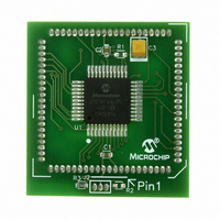
MA180023 Microchip Technology, MA180023 Datasheet - Page 205

MA180023
Manufacturer Part Number
MA180023
Description
MODULE PLUG-IN PIC18F46J11 PIM
Manufacturer
Microchip Technology
Series
PIC®r
Datasheet
1.MA180023.pdf
(528 pages)
Specifications of MA180023
Accessory Type
Plug-In Module (PIM) - PIC18F46J11
Tool / Board Applications
General Purpose MCU, MPU, DSP, DSC
Mcu Supported Families
PIC18
Supported Devices
Stand-alone Or W/ HPC(DM183022) Or PIC18(DM183032)
Silicon Manufacturer
Microchip
Core Architecture
PIC
Core Sub-architecture
PIC18
Silicon Core Number
PIC18F
Silicon Family Name
PIC18FxxJxx
Lead Free Status / RoHS Status
Lead free / RoHS Compliant
For Use With/related Products
HPC Explorer Board (DM183022) or PIC18 Explorer Board (DM183032)
For Use With
DM183032 - BOARD EXPLORER PICDEM PIC18DM183022 - BOARD DEMO PIC18FXX22 64/80TQFP
Lead Free Status / RoHS Status
Lead free / RoHS Compliant
Available stocks
Company
Part Number
Manufacturer
Quantity
Price
Company:
Part Number:
MA180023
Manufacturer:
Microchip Technology
Quantity:
135
- Current page: 205 of 528
- Download datasheet (8Mb)
12.8.4
When Timer1 Gate Single Pulse mode is enabled, it is
possible to capture a single pulse gate event. Timer1
Gate Single Pulse mode is first enabled by setting the
T1GSPM bit in the T1GCON register. Next, the
T1GGO/T1DONE bit in the T1GCON register must be
set. The Timer1 will be fully enabled on the next incre-
menting edge. On the next trailing edge of the pulse,
the T1GGO/T1DONE bit will automatically be cleared.
No other gate events will be allowed to increment
Timer1 until the T1GGO/T1DONE bit is once again set
in software.
FIGURE 12-6:
© 2009 Microchip Technology Inc.
TMR1GE
T1GSPM
T1DONE
T1GPOL
T1GVAL
T1GGO/
RTCCIF
T1G_IN
Timer1
T1CKI
TIMER1 GATE SINGLE PULSE
MODE
TIMER1 GATE SINGLE PULSE MODE
Cleared by Software
N
Counting Enabled on
Rising Edge of T1G
Set by Software
N + 1
PIC18F46J11 FAMILY
Clearing the T1GSPM bit of the T1GCON register will
also clear the T1GGO/T1DONE bit. See Figure 12-6
for timing details.
Enabling the Toggle mode and the Single Pulse mode,
simultaneously, will permit both sections to work together.
This allows the cycle times on the Timer1 gate source to
be measured. See Figure 12-7 for timing details.
12.8.5
When the Timer1 gate value status is utilized, it is
possible to read the most current level of the gate
control value. The value is stored in the T1GVAL bit in
the T1GCON register. The T1GVAL bit is valid even
when the Timer1 gate is not enabled (TMR1GE bit is
cleared).
Set by Hardware on
Falling Edge of T1GVAL
Cleared by Hardware on
Falling Edge of T1GVAL
TIMER1 GATE VALUE STATUS
N + 2
DS39932C-page 205
Cleared by
Software
Related parts for MA180023
Image
Part Number
Description
Manufacturer
Datasheet
Request
R

Part Number:
Description:
Manufacturer:
Microchip Technology Inc.
Datasheet:

Part Number:
Description:
Manufacturer:
Microchip Technology Inc.
Datasheet:

Part Number:
Description:
Manufacturer:
Microchip Technology Inc.
Datasheet:

Part Number:
Description:
Manufacturer:
Microchip Technology Inc.
Datasheet:

Part Number:
Description:
Manufacturer:
Microchip Technology Inc.
Datasheet:

Part Number:
Description:
Manufacturer:
Microchip Technology Inc.
Datasheet:

Part Number:
Description:
Manufacturer:
Microchip Technology Inc.
Datasheet:

Part Number:
Description:
Manufacturer:
Microchip Technology Inc.
Datasheet:


