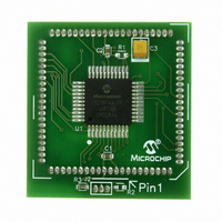
MA180023 Microchip Technology, MA180023 Datasheet - Page 324

MA180023
Manufacturer Part Number
MA180023
Description
MODULE PLUG-IN PIC18F46J11 PIM
Manufacturer
Microchip Technology
Series
PIC®r
Datasheet
1.MA180023.pdf
(528 pages)
Specifications of MA180023
Accessory Type
Plug-In Module (PIM) - PIC18F46J11
Tool / Board Applications
General Purpose MCU, MPU, DSP, DSC
Mcu Supported Families
PIC18
Supported Devices
Stand-alone Or W/ HPC(DM183022) Or PIC18(DM183032)
Silicon Manufacturer
Microchip
Core Architecture
PIC
Core Sub-architecture
PIC18
Silicon Core Number
PIC18F
Silicon Family Name
PIC18FxxJxx
Lead Free Status / RoHS Status
Lead free / RoHS Compliant
For Use With/related Products
HPC Explorer Board (DM183022) or PIC18 Explorer Board (DM183032)
For Use With
DM183032 - BOARD EXPLORER PICDEM PIC18DM183022 - BOARD DEMO PIC18FXX22 64/80TQFP
Lead Free Status / RoHS Status
Lead free / RoHS Compliant
Available stocks
Company
Part Number
Manufacturer
Quantity
Price
Company:
Part Number:
MA180023
Manufacturer:
Microchip Technology
Quantity:
135
- Current page: 324 of 528
- Download datasheet (8Mb)
PIC18F46J11 FAMILY
REGISTER 19-3:
DS39932C-page 324
bit 7
Legend:
R = Readable bit
-n = Value at POR
bit 7
bit 6
bit 5
bit 4
bit 3
bit 2
bit 1
bit 0
ABDOVF
R/W-0
ABDOVF: Auto-Baud Acquisition Rollover Status bit
1 = A BRG rollover has occurred during Auto-Baud Rate Detect mode (must be cleared in software)
0 = No BRG rollover has occurred
RCIDL: Receive Operation Idle Status bit
1 = Receive operation is Idle
0 = Receive operation is active
RXDTP: Data/Receive Polarity Select bit
Asynchronous mode:
1 = Receive data (RXx) is inverted (active-low)
0 = Receive data (RXx) is not inverted (active-high)
Synchronous mode:
1 = Data (DTx) is inverted (active-low)
0 = Data (DTx) is not inverted (active-high)
TXCKP: Synchronous Clock Polarity Select bit
Asynchronous mode:
1 = Idle state for transmit (TXx) is a low level
0 = Idle state for transmit (TXx) is a high level
Synchronous mode:
1 = Idle state for clock (CKx) is a high level
0 = Idle state for clock (CKx) is a low level
BRG16: 16-Bit Baud Rate Register Enable bit
1 = 16-bit Baud Rate Generator – SPBRGHx and SPBRGx
0 = 8-bit Baud Rate Generator – SPBRGx only (Compatible mode), SPBRGHx value ignored
Unimplemented: Read as ‘0’
WUE: Wake-up Enable bit
Asynchronous mode:
1 = EUSART will continue to sample the RXx pin – interrupt generated on falling edge; bit cleared in
0 = RXx pin not monitored or rising edge detected
Synchronous mode:
Unused in this mode.
ABDEN: Auto-Baud Detect Enable bit
Asynchronous mode:
1 = Enable baud rate measurement on the next character; requires reception of a Sync field (55h);
0 = Baud rate measurement disabled or completed
Synchronous mode:
Unused in this mode.
RCIDL
hardware on following rising edge
cleared in hardware upon completion
R-1
BAUDCONx: BAUD RATE CONTROL REGISTER (ACCESS F7Eh/F7Ch)
W = Writable bit
‘1’ = Bit is set
RXDTP
R/W-0
TXCKP
R/W-0
U = Unimplemented bit, read as ‘0’
‘0’ = Bit is cleared
BRG16
R/W-0
U-0
—
© 2009 Microchip Technology Inc.
x = Bit is unknown
R/W-0
WUE
ABDEN
R/W-0
bit 0
Related parts for MA180023
Image
Part Number
Description
Manufacturer
Datasheet
Request
R

Part Number:
Description:
Manufacturer:
Microchip Technology Inc.
Datasheet:

Part Number:
Description:
Manufacturer:
Microchip Technology Inc.
Datasheet:

Part Number:
Description:
Manufacturer:
Microchip Technology Inc.
Datasheet:

Part Number:
Description:
Manufacturer:
Microchip Technology Inc.
Datasheet:

Part Number:
Description:
Manufacturer:
Microchip Technology Inc.
Datasheet:

Part Number:
Description:
Manufacturer:
Microchip Technology Inc.
Datasheet:

Part Number:
Description:
Manufacturer:
Microchip Technology Inc.
Datasheet:

Part Number:
Description:
Manufacturer:
Microchip Technology Inc.
Datasheet:


