C8051F326DK Silicon Laboratories Inc, C8051F326DK Datasheet - Page 18
C8051F326DK
Manufacturer Part Number
C8051F326DK
Description
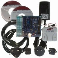
KIT DEV FOR C8051F326/7
Manufacturer
Silicon Laboratories Inc
Type
MCUr
Specifications of C8051F326DK
Contents
Evaluation Board, Power Supply, USB Cables, Adapter and Documentation
Processor To Be Evaluated
C8051F326/F327
Interface Type
USB
Silicon Manufacturer
Silicon Labs
Core Architecture
8051
Silicon Core Number
C8051F326
Silicon Family Name
C8051F32x
Lead Free Status / RoHS Status
Contains lead / RoHS non-compliant
For Use With/related Products
Silicon Laboratories C8051F326, C8051F327
Lead Free Status / Rohs Status
Lead free / RoHS Compliant
Other names
336-1306


C8051F326/7
1.1.3. Additional Features
The C8051F326/7 SoC family includes several key enhancements to the CIP-51 core and peripherals to
improve performance and ease of use in end applications.
The extended interrupt handler provides 8 interrupt sources into the CIP-51. An interrupt driven system
requires less intervention by the MCU, giving it more effective throughput. The interrupt sources are very
useful when building multi-tasking, real-time systems.
Seven reset sources are available: power-on reset circuitry (POR), an on-chip VDD monitor (forces reset
when power supply voltage drops below V
bus reset or a VBUS transition), a Missing Clock Detector, a forced software reset, an external reset pin,
and an errant Flash read/write protection circuit. Each reset source except for the POR, Reset Input Pin, or
Flash error may be disabled by the user in software.
The internal oscillator is factory calibrated to 12 MHz ±1.5%, and the internal oscillator period may be user
programmed in ~0.25% increments. An additional low-frequency oscillator is also available which facili-
tates low power operation. A clock recovery mechanism allows the internal oscillator to be used with the 4x
Clock Multiplier as the USB clock source in Full Speed mode; the internal oscillator can also be used as
the USB clock source in Low Speed mode. An external CMOS clock may also be used with the 4x Clock
Multiplier. The system clock may be configured to use the internal oscillator, external clock, low-frequency
oscillator, or the Clock Multiplier output divided by 2. If desired, the system clock source may be switched
on-the-fly between oscillator sources. The external clock and internal low-frequency oscillator can be
extremely useful in low power applications, allowing the MCU to run from a slow (power saving) clock
source, while periodically switching to the high-frequency internal oscillator as needed.
18
XTAL2
Clock Input
Frequency
Oscillator
Oscillator
External
Internal
Low
Clock Select
System
Clock
Figure 1.6. On-Chip Clock and Reset
Detector
M issing
Clock
(one-
shot)
M icrocontroller
EN
Extended Interrupt
RST
CIP-51
Handler
Core
VDD
as given in Table 7.1 on page 62), the USB controller (USB
Rev. 1.1
Supply
Monitor
+
-
System Reset
Enable
Power On
Reset
(Software Reset)
SW RSF
'0'
Operation
FLASH
Errant
(wired-OR)
Reset
Funnel
/RST
Related parts for C8051F326DK
Image
Part Number
Description
Manufacturer
Datasheet
Request
R

Part Number:
Description:
SMD/C°/SINGLE-ENDED OUTPUT SILICON OSCILLATOR
Manufacturer:
Silicon Laboratories Inc
Part Number:
Description:
Manufacturer:
Silicon Laboratories Inc
Datasheet:
Part Number:
Description:
N/A N/A/SI4010 AES KEYFOB DEMO WITH LCD RX
Manufacturer:
Silicon Laboratories Inc
Datasheet:
Part Number:
Description:
N/A N/A/SI4010 SIMPLIFIED KEY FOB DEMO WITH LED RX
Manufacturer:
Silicon Laboratories Inc
Datasheet:
Part Number:
Description:
N/A/-40 TO 85 OC/EZLINK MODULE; F930/4432 HIGH BAND (REV E/B1)
Manufacturer:
Silicon Laboratories Inc
Part Number:
Description:
EZLink Module; F930/4432 Low Band (rev e/B1)
Manufacturer:
Silicon Laboratories Inc
Part Number:
Description:
I°/4460 10 DBM RADIO TEST CARD 434 MHZ
Manufacturer:
Silicon Laboratories Inc
Part Number:
Description:
I°/4461 14 DBM RADIO TEST CARD 868 MHZ
Manufacturer:
Silicon Laboratories Inc
Part Number:
Description:
I°/4463 20 DBM RFSWITCH RADIO TEST CARD 460 MHZ
Manufacturer:
Silicon Laboratories Inc
Part Number:
Description:
I°/4463 20 DBM RADIO TEST CARD 868 MHZ
Manufacturer:
Silicon Laboratories Inc
Part Number:
Description:
I°/4463 27 DBM RADIO TEST CARD 868 MHZ
Manufacturer:
Silicon Laboratories Inc
Part Number:
Description:
I°/4463 SKYWORKS 30 DBM RADIO TEST CARD 915 MHZ
Manufacturer:
Silicon Laboratories Inc
Part Number:
Description:
N/A N/A/-40 TO 85 OC/4463 RFMD 30 DBM RADIO TEST CARD 915 MHZ
Manufacturer:
Silicon Laboratories Inc
Part Number:
Description:
I°/4463 20 DBM RADIO TEST CARD 169 MHZ
Manufacturer:
Silicon Laboratories Inc