C8051F326DK Silicon Laboratories Inc, C8051F326DK Datasheet - Page 76
C8051F326DK
Manufacturer Part Number
C8051F326DK
Description
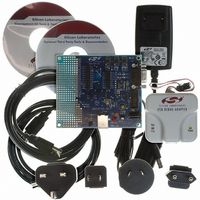
KIT DEV FOR C8051F326/7
Manufacturer
Silicon Laboratories Inc
Type
MCUr
Specifications of C8051F326DK
Contents
Evaluation Board, Power Supply, USB Cables, Adapter and Documentation
Processor To Be Evaluated
C8051F326/F327
Interface Type
USB
Silicon Manufacturer
Silicon Labs
Core Architecture
8051
Silicon Core Number
C8051F326
Silicon Family Name
C8051F32x
Lead Free Status / RoHS Status
Contains lead / RoHS non-compliant
For Use With/related Products
Silicon Laboratories C8051F326, C8051F327
Lead Free Status / Rohs Status
Lead free / RoHS Compliant
Other names
336-1306


C8051F326/7
10.5. System and USB Clock Selection
The internal oscillator requires little start-up time and may be selected as the system or USB clock immedi-
ately following the OSCICN write that enables the internal oscillator. If the external clock is selected as the
system or USB clock, then startup times may vary based on the specifications of the external clock.
10.5.1. System Clock Selection
The CLKSL[2:0] bits in register CLKSEL select which oscillator source is used as the system clock.
CLKSL[2:0] must be set to 001b for the system clock to run from the external clock; however the external
clock may still clock certain peripherals (timers, UART, USB) when the internal oscillator is selected as the
system clock. The system clock may be switched on-the-fly between the internal oscillator, external clock,
low frequency oscillator, and 4x Clock Multiplier so long as the selected oscillator is enabled and can pro-
vide a stable clock.
10.5.2. USB Clock Selection
The USBCLK[1:0] bits in register CLKSEL select which oscillator source is used as the USB clock. The
USB clock may be derived from the 4x Clock Multiplier output, internal oscillator divided by 2, or an exter-
nal clock. The USB clock source may also be turned off. The USB clock must be 48 MHz when operating
USB0 as a Full Speed Function; the USB clock must be 6 MHz when operating USB0 as a Low Speed
Function. See Figure 10.5 for USB clock selection options.
Some example USB clock configurations for Full and Low Speed mode are given below:
76
USB Clock
Clock Multiplier Input
Internal Oscillator
USB Clock
Clock Multiplier Input
Port I/O
*Note: Clock Recovery must be enabled for this configuration.
USB Clock
Internal Oscillator
USB Clock
Port I/O
Clock Signal
Clock Signal
Clock Signal
Clock Signal
Table 10.2. Typical USB Low Speed Clock Settings
Table 10.1. Typical USB Full Speed Clock Settings
Clock Multiplier
Internal Oscillator*
Divide by 1
Clock Multiplier
External Clock
12 MHz CMOS Clock
Internal Oscillator / 2
Divide by 1
External Clock
6 MHz CMOS Clock
Input Source Selection
Input Source Selection
Input Source Selection
Input Source Selection
Internal Oscillator
Internal Oscillator
External Clock
External Clock
Rev. 1.1
USBCLK = 00b
MULSEL = 0b
IFCN = 11b
USBCLK = 10b
MULSEL = 1b
INPUTEN = 1b (GPI-
OCN.6)
USBCLK = 01b
IFCN = 11b
USBCLK = 10b
INPUTEN = 1b (GPI-
OCN.6)
Register Bit Settings
Register Bit Settings
Register Bit Settings
Register Bit Settings
Related parts for C8051F326DK
Image
Part Number
Description
Manufacturer
Datasheet
Request
R

Part Number:
Description:
SMD/C°/SINGLE-ENDED OUTPUT SILICON OSCILLATOR
Manufacturer:
Silicon Laboratories Inc
Part Number:
Description:
Manufacturer:
Silicon Laboratories Inc
Datasheet:
Part Number:
Description:
N/A N/A/SI4010 AES KEYFOB DEMO WITH LCD RX
Manufacturer:
Silicon Laboratories Inc
Datasheet:
Part Number:
Description:
N/A N/A/SI4010 SIMPLIFIED KEY FOB DEMO WITH LED RX
Manufacturer:
Silicon Laboratories Inc
Datasheet:
Part Number:
Description:
N/A/-40 TO 85 OC/EZLINK MODULE; F930/4432 HIGH BAND (REV E/B1)
Manufacturer:
Silicon Laboratories Inc
Part Number:
Description:
EZLink Module; F930/4432 Low Band (rev e/B1)
Manufacturer:
Silicon Laboratories Inc
Part Number:
Description:
I°/4460 10 DBM RADIO TEST CARD 434 MHZ
Manufacturer:
Silicon Laboratories Inc
Part Number:
Description:
I°/4461 14 DBM RADIO TEST CARD 868 MHZ
Manufacturer:
Silicon Laboratories Inc
Part Number:
Description:
I°/4463 20 DBM RFSWITCH RADIO TEST CARD 460 MHZ
Manufacturer:
Silicon Laboratories Inc
Part Number:
Description:
I°/4463 20 DBM RADIO TEST CARD 868 MHZ
Manufacturer:
Silicon Laboratories Inc
Part Number:
Description:
I°/4463 27 DBM RADIO TEST CARD 868 MHZ
Manufacturer:
Silicon Laboratories Inc
Part Number:
Description:
I°/4463 SKYWORKS 30 DBM RADIO TEST CARD 915 MHZ
Manufacturer:
Silicon Laboratories Inc
Part Number:
Description:
N/A N/A/-40 TO 85 OC/4463 RFMD 30 DBM RADIO TEST CARD 915 MHZ
Manufacturer:
Silicon Laboratories Inc
Part Number:
Description:
I°/4463 20 DBM RADIO TEST CARD 169 MHZ
Manufacturer:
Silicon Laboratories Inc