C8051F326DK Silicon Laboratories Inc, C8051F326DK Datasheet - Page 55
C8051F326DK
Manufacturer Part Number
C8051F326DK
Description
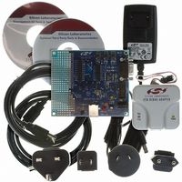
KIT DEV FOR C8051F326/7
Manufacturer
Silicon Laboratories Inc
Type
MCUr
Specifications of C8051F326DK
Contents
Evaluation Board, Power Supply, USB Cables, Adapter and Documentation
Processor To Be Evaluated
C8051F326/F327
Interface Type
USB
Silicon Manufacturer
Silicon Labs
Core Architecture
8051
Silicon Core Number
C8051F326
Silicon Family Name
C8051F32x
Lead Free Status / RoHS Status
Contains lead / RoHS non-compliant
For Use With/related Products
Silicon Laboratories C8051F326, C8051F327
Lead Free Status / Rohs Status
Lead free / RoHS Compliant
Other names
336-1306


C8051F326/7
6.4.
Power Management Modes
The CIP-51 core has two software programmable power management modes: Idle and Stop. Idle mode
halts the CPU while leaving the peripherals and clocks active. In Stop mode, the CPU is halted, all inter-
rupts, are inactive, and the internal oscillator is stopped (the voltage regulator, low frequency oscillator, and
external clock remain in their selected state). Since clocks are running in Idle mode, power consumption is
dependent upon the system clock frequency and the number of peripherals left in active mode before
entering Idle. Stop mode consumes the least power. Figure 6.13 describes the Power Control Register
(PCON) used to control the CIP-51's power management modes.
Although the CIP-51 has Idle and Stop modes built in (as with any standard 8051 architecture), power
management of the entire MCU is better accomplished through system clock and individual peripheral
management. Digital peripherals, such as timers or UART, draw little power when they are not in use. Turn-
ing off the oscillators lowers power consumption considerably; however a reset is required to restart the
MCU.
The internal oscillator can be placed in Suspend mode (see Section “10. Oscillators” on page 71). In Sus-
pend mode, the internal oscillator is stopped until a non-idle USB event is detected, or the VBUS input sig-
nal matches the polarity selected by the VBPOL bit in register REG0CN (Figure 5.1 on Page 34).
6.4.1. Idle Mode
Setting the Idle Mode Select bit (PCON.0) causes the CIP-51 to halt the CPU and enter Idle mode as soon
as the instruction that sets the bit completes execution. All internal registers and memory maintain their
original data. All analog and digital peripherals can remain active during Idle mode.
Idle mode is terminated when an enabled interrupt is asserted or a reset occurs. The assertion of an
enabled interrupt will cause the Idle Mode Selection bit (PCON.0) to be cleared and the CPU to resume
operation. The pending interrupt will be serviced and the next instruction to be executed after the return
from interrupt (RETI) will be the instruction immediately following the one that set the Idle Mode Select bit.
If Idle mode is terminated by an internal or external reset, the CIP-51 performs a normal reset sequence
and begins program execution at address 0x0000.
6.4.2. Stop Mode
Setting the Stop Mode Select bit (PCON.1) causes the CIP-51 to enter Stop mode as soon as the instruc-
tion that sets the bit completes execution. In Stop mode the internal oscillator, CPU, and all digital peripher-
als are stopped; the state of the low frequency oscillator is not affected. Each analog peripheral (including
the low frequency oscillator) may be shut down individually prior to entering Stop Mode. Stop mode can
only be terminated by an internal or external reset. On reset, the CIP-51 performs the normal reset
sequence and begins program execution at address 0x0000.
If enabled, the Missing Clock Detector will cause an internal reset and thereby terminate the Stop mode.
The Missing Clock Detector should be disabled if the CPU is to be put to in STOP mode for longer than the
MCD timeout of 100 µs.
Rev. 1.1
55
Related parts for C8051F326DK
Image
Part Number
Description
Manufacturer
Datasheet
Request
R

Part Number:
Description:
SMD/C°/SINGLE-ENDED OUTPUT SILICON OSCILLATOR
Manufacturer:
Silicon Laboratories Inc
Part Number:
Description:
Manufacturer:
Silicon Laboratories Inc
Datasheet:
Part Number:
Description:
N/A N/A/SI4010 AES KEYFOB DEMO WITH LCD RX
Manufacturer:
Silicon Laboratories Inc
Datasheet:
Part Number:
Description:
N/A N/A/SI4010 SIMPLIFIED KEY FOB DEMO WITH LED RX
Manufacturer:
Silicon Laboratories Inc
Datasheet:
Part Number:
Description:
N/A/-40 TO 85 OC/EZLINK MODULE; F930/4432 HIGH BAND (REV E/B1)
Manufacturer:
Silicon Laboratories Inc
Part Number:
Description:
EZLink Module; F930/4432 Low Band (rev e/B1)
Manufacturer:
Silicon Laboratories Inc
Part Number:
Description:
I°/4460 10 DBM RADIO TEST CARD 434 MHZ
Manufacturer:
Silicon Laboratories Inc
Part Number:
Description:
I°/4461 14 DBM RADIO TEST CARD 868 MHZ
Manufacturer:
Silicon Laboratories Inc
Part Number:
Description:
I°/4463 20 DBM RFSWITCH RADIO TEST CARD 460 MHZ
Manufacturer:
Silicon Laboratories Inc
Part Number:
Description:
I°/4463 20 DBM RADIO TEST CARD 868 MHZ
Manufacturer:
Silicon Laboratories Inc
Part Number:
Description:
I°/4463 27 DBM RADIO TEST CARD 868 MHZ
Manufacturer:
Silicon Laboratories Inc
Part Number:
Description:
I°/4463 SKYWORKS 30 DBM RADIO TEST CARD 915 MHZ
Manufacturer:
Silicon Laboratories Inc
Part Number:
Description:
N/A N/A/-40 TO 85 OC/4463 RFMD 30 DBM RADIO TEST CARD 915 MHZ
Manufacturer:
Silicon Laboratories Inc
Part Number:
Description:
I°/4463 20 DBM RADIO TEST CARD 169 MHZ
Manufacturer:
Silicon Laboratories Inc