C8051F560-TB Silicon Laboratories Inc, C8051F560-TB Datasheet - Page 155
C8051F560-TB
Manufacturer Part Number
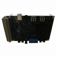
C8051F560-TB
Description
BOARD PROTOTYPE W/C8051F560
Manufacturer
Silicon Laboratories Inc
Type
MCUr
Datasheet
1.TOOLSTICK560DC.pdf
(302 pages)
Specifications of C8051F560-TB
Contents
Board
Processor To Be Evaluated
C8051F56x
Processor Series
C8051F56x
Interface Type
USB
Maximum Operating Temperature
+ 125 C
Minimum Operating Temperature
- 40 C
Operating Supply Voltage
1.8 V to 5.25 V
Lead Free Status / RoHS Status
Lead free / RoHS Compliant
For Use With/related Products
C8051F55x, C8051F56x, C8051F57x
For Use With
336-1691 - KIT DEVELOPMENT FOR C8051F560
Lead Free Status / Rohs Status
Lead free / RoHS Compliant
Other names
336-1694


18. Oscillators and Clock Selection
C8051F55x/56x/57x devices include a programmable internal high-frequency oscillator, an external oscil-
lator drive circuit, and a clock multiplier. The internal oscillator can be enabled/disabled and calibrated
using the OSCICN, OSCICRS, and OSCIFIN registers, as shown in Figure 18.1. The system clock can be
sourced by the external oscillator circuit or the internal oscillator. The clock multiplier can produce three
possible base outputs which can be scaled by a programmable factor of 1, 2/3, 2/4 (or 1/2), 2/5, 2/6 (or
1/3), or 2/7: Internal Oscillator x 2, Internal Oscillator x 4, External Oscillator x 2, or External Oscillator x 4.
18.1. System Clock Selection
The CLKSL[1:0] bits in register CLKSEL select which oscillator source is used as the system clock.
CLKSL[1:0] must be set to 01b for the system clock to run from the external oscillator; however the exter-
nal oscillator may still clock certain peripherals (timers, PCA) when the internal oscillator is selected as the
system clock. The system clock may be switched on-the-fly between the internal oscillator, external oscilla-
tor, and Clock Multiplier so long as the selected clock source is enabled and has settled.
The internal oscillator requires little start-up time and may be selected as the system clock immediately fol-
lowing the register write which enables the oscillator. The external RC and C modes also typically require
no startup time.
External crystals and ceramic resonators however, typically require a start-up time before they are settled
and ready for use. The Crystal Valid Flag (XTLVLD in register OSCXCN) is set to 1 by hardware when the
external crystal or ceramic resonator is settled. In crystal mode, to avoid reading a false XTLVLD, soft-
ware should delay at least 1 ms between enabling the external oscillator and checking XTLVLD.
VDD
Option 2
Option 3
XTAL2
XTAL2
Option 1
Option 4
XTAL2
10M
XTAL1
XTAL2
Figure 18.1. Oscillator Options
OSCICRS
Programmable Internal
Circuit
Rev. 1.1
Input
CAL
Clock Generator
OSCXCN
OSCIFIN
EXOSC / 2
EXTOSC
IOSC / 2
OSC
IOSC
EN
EXOSC
C8051F55x/56x/57x
OSCICN
CLOCK MULTIPLIER
IOSC
x4
CLKMUL
n
n
CLKSEL
SYSCLK
155
Related parts for C8051F560-TB
Image
Part Number
Description
Manufacturer
Datasheet
Request
R

Part Number:
Description:
SMD/C°/SINGLE-ENDED OUTPUT SILICON OSCILLATOR
Manufacturer:
Silicon Laboratories Inc
Part Number:
Description:
Manufacturer:
Silicon Laboratories Inc
Datasheet:
Part Number:
Description:
N/A N/A/SI4010 AES KEYFOB DEMO WITH LCD RX
Manufacturer:
Silicon Laboratories Inc
Datasheet:
Part Number:
Description:
N/A N/A/SI4010 SIMPLIFIED KEY FOB DEMO WITH LED RX
Manufacturer:
Silicon Laboratories Inc
Datasheet:
Part Number:
Description:
N/A/-40 TO 85 OC/EZLINK MODULE; F930/4432 HIGH BAND (REV E/B1)
Manufacturer:
Silicon Laboratories Inc
Part Number:
Description:
EZLink Module; F930/4432 Low Band (rev e/B1)
Manufacturer:
Silicon Laboratories Inc
Part Number:
Description:
I°/4460 10 DBM RADIO TEST CARD 434 MHZ
Manufacturer:
Silicon Laboratories Inc
Part Number:
Description:
I°/4461 14 DBM RADIO TEST CARD 868 MHZ
Manufacturer:
Silicon Laboratories Inc
Part Number:
Description:
I°/4463 20 DBM RFSWITCH RADIO TEST CARD 460 MHZ
Manufacturer:
Silicon Laboratories Inc
Part Number:
Description:
I°/4463 20 DBM RADIO TEST CARD 868 MHZ
Manufacturer:
Silicon Laboratories Inc
Part Number:
Description:
I°/4463 27 DBM RADIO TEST CARD 868 MHZ
Manufacturer:
Silicon Laboratories Inc
Part Number:
Description:
I°/4463 SKYWORKS 30 DBM RADIO TEST CARD 915 MHZ
Manufacturer:
Silicon Laboratories Inc
Part Number:
Description:
N/A N/A/-40 TO 85 OC/4463 RFMD 30 DBM RADIO TEST CARD 915 MHZ
Manufacturer:
Silicon Laboratories Inc
Part Number:
Description:
I°/4463 20 DBM RADIO TEST CARD 169 MHZ
Manufacturer:
Silicon Laboratories Inc