C8051F560-TB Silicon Laboratories Inc, C8051F560-TB Datasheet - Page 233
C8051F560-TB
Manufacturer Part Number
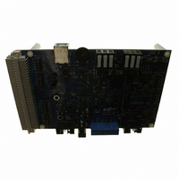
C8051F560-TB
Description
BOARD PROTOTYPE W/C8051F560
Manufacturer
Silicon Laboratories Inc
Type
MCUr
Datasheet
1.TOOLSTICK560DC.pdf
(302 pages)
Specifications of C8051F560-TB
Contents
Board
Processor To Be Evaluated
C8051F56x
Processor Series
C8051F56x
Interface Type
USB
Maximum Operating Temperature
+ 125 C
Minimum Operating Temperature
- 40 C
Operating Supply Voltage
1.8 V to 5.25 V
Lead Free Status / RoHS Status
Lead free / RoHS Compliant
For Use With/related Products
C8051F55x, C8051F56x, C8051F57x
For Use With
336-1691 - KIT DEVELOPMENT FOR C8051F560
Lead Free Status / Rohs Status
Lead free / RoHS Compliant
Other names
336-1694


23. UART0
UART0 is an asynchronous, full duplex serial port offering a variety of data formatting options. A dedicated
baud rate generator with a 16-bit timer and selectable prescaler is included, which can generate a wide
range of baud rates (details in Section “23.1. Baud Rate Generator” on page 233). A received data FIFO
allows UART0 to receive up to three data bytes before data is lost and an overflow occurs.
UART0 has six associated SFRs. Three are used for the Baud Rate Generator (SBCON0, SBRLH0, and
SBRLL0), two are used for data formatting, control, and status functions (SCON0, SMOD0), and one is
used to send and receive data (SBUF0). The single SBUF0 location provides access to both the transmit
holding register and the receive FIFO. Writes to SBUF0 always access the Transmit register. Reads of
SBUF0 always access the first byte of the Receive FIFO; it is not possible to read data from the
Transmit Holding Register.
With UART0 interrupts enabled, an interrupt is generated each time a transmit is completed (TI0 is set in
SCON0), or a data byte has been received (RI0 is set in SCON0). The UART0 interrupt flags are not
cleared by hardware when the CPU vectors to the interrupt service routine. They must be cleared manually
by software, allowing software to determine the cause of the UART0 interrupt (transmit complete or receive
complete). If additional bytes are available in the Receive FIFO, the RI0 bit cannot be cleared by software.
23.1. Baud Rate Generator
The UART0 baud rate is generated by a dedicated 16-bit timer which runs from the controller’s core clock
(SYSCLK) and has prescaler options of 1, 4, 12, or 48. The timer and prescaler options combined allow for
a wide selection of baud rates over many clock frequencies.
The baud rate generator is configured using three registers: SBCON0, SBRLH0, and SBRLL0. The
UART0 Baud Rate Generator Control Register (SBCON0, SFR Definition 23.4) enables or disables the
baud rate generator and selects the prescaler value for the timer. The baud rate generator must be
enabled for UART0 to function. Registers SBRLH0 and SBRLL0 contain a 16-bit reload value for the dedi-
cated 16-bit timer. The internal timer counts up from the reload value on every clock tick. On timer over-
flows (0xFFFF to 0x0000), the timer is reloaded. The baud rate for UART0 is defined in Equation 23.1,
where “BRG Clock” is the baud rate generator’s selected clock source. For reliable UART operation, it is
recommended that the UART baud rate is not configured for baud rates faster than SYSCLK/16.
SYSCLK
SBRLH0
Timer (16-bit)
Baud Rate Generator
SBRLL0
EN
SBCON0
Figure 23.1. UART0 Block Diagram
Overflow
(1, 4, 12, 48)
Pre-Scaler
Rev. 1.1
Data Formatting
Control / Status
Interrupt
UART0
SMOD0
SCON0
C8051F55x/56x/57x
TX Holding
RX FIFO
(3 Deep)
Register
SBUF0
Logic
Logic
RX
TX
Write to SBUF0
Read of SBUF0
TX0
RX0
233
Related parts for C8051F560-TB
Image
Part Number
Description
Manufacturer
Datasheet
Request
R

Part Number:
Description:
SMD/C°/SINGLE-ENDED OUTPUT SILICON OSCILLATOR
Manufacturer:
Silicon Laboratories Inc
Part Number:
Description:
Manufacturer:
Silicon Laboratories Inc
Datasheet:
Part Number:
Description:
N/A N/A/SI4010 AES KEYFOB DEMO WITH LCD RX
Manufacturer:
Silicon Laboratories Inc
Datasheet:
Part Number:
Description:
N/A N/A/SI4010 SIMPLIFIED KEY FOB DEMO WITH LED RX
Manufacturer:
Silicon Laboratories Inc
Datasheet:
Part Number:
Description:
N/A/-40 TO 85 OC/EZLINK MODULE; F930/4432 HIGH BAND (REV E/B1)
Manufacturer:
Silicon Laboratories Inc
Part Number:
Description:
EZLink Module; F930/4432 Low Band (rev e/B1)
Manufacturer:
Silicon Laboratories Inc
Part Number:
Description:
I°/4460 10 DBM RADIO TEST CARD 434 MHZ
Manufacturer:
Silicon Laboratories Inc
Part Number:
Description:
I°/4461 14 DBM RADIO TEST CARD 868 MHZ
Manufacturer:
Silicon Laboratories Inc
Part Number:
Description:
I°/4463 20 DBM RFSWITCH RADIO TEST CARD 460 MHZ
Manufacturer:
Silicon Laboratories Inc
Part Number:
Description:
I°/4463 20 DBM RADIO TEST CARD 868 MHZ
Manufacturer:
Silicon Laboratories Inc
Part Number:
Description:
I°/4463 27 DBM RADIO TEST CARD 868 MHZ
Manufacturer:
Silicon Laboratories Inc
Part Number:
Description:
I°/4463 SKYWORKS 30 DBM RADIO TEST CARD 915 MHZ
Manufacturer:
Silicon Laboratories Inc
Part Number:
Description:
N/A N/A/-40 TO 85 OC/4463 RFMD 30 DBM RADIO TEST CARD 915 MHZ
Manufacturer:
Silicon Laboratories Inc
Part Number:
Description:
I°/4463 20 DBM RADIO TEST CARD 169 MHZ
Manufacturer:
Silicon Laboratories Inc