C8051F560-TB Silicon Laboratories Inc, C8051F560-TB Datasheet - Page 284
C8051F560-TB
Manufacturer Part Number
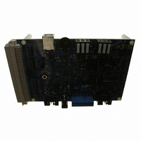
C8051F560-TB
Description
BOARD PROTOTYPE W/C8051F560
Manufacturer
Silicon Laboratories Inc
Type
MCUr
Datasheet
1.TOOLSTICK560DC.pdf
(302 pages)
Specifications of C8051F560-TB
Contents
Board
Processor To Be Evaluated
C8051F56x
Processor Series
C8051F56x
Interface Type
USB
Maximum Operating Temperature
+ 125 C
Minimum Operating Temperature
- 40 C
Operating Supply Voltage
1.8 V to 5.25 V
Lead Free Status / RoHS Status
Lead free / RoHS Compliant
For Use With/related Products
C8051F55x, C8051F56x, C8051F57x
For Use With
336-1691 - KIT DEVELOPMENT FOR C8051F560
Lead Free Status / Rohs Status
Lead free / RoHS Compliant
Other names
336-1694


C8051F55x/56x/57x
26.3.5. 8-bit, 9-bit, 10-bit and 11-bit Pulse Width Modulator Modes
Each module can be used independently to generate a pulse width modulated (PWM) output on its associ-
ated CEXn pin. The frequency of the output is dependent on the timebase for the PCA counter/timer, and
the setting of the PWM cycle length (8, 9, 10 or 11-bits). For backwards-compatibility with the 8-bit PWM
mode available on other devices, the 8-bit PWM mode operates slightly different than 9, 10 and 11-bit
PWM modes. It is important to note that all channels configured for 8/9/10/11-bit PWM mode will use
the same cycle length. It is not possible to configure one channel for 8-bit PWM mode and another for 11-
bit mode (for example). However, other PCA channels can be configured to Pin Capture, High-Speed Out-
put, Software Timer, Frequency Output, or 16-bit PWM mode independently.
26.3.5.1. 8-bit Pulse Width Modulator Mode
The duty cycle of the PWM output signal in 8-bit PWM mode is varied using the module's PCA0CPLn cap-
ture/compare register. When the value in the low byte of the PCA counter/timer (PCA0L) is equal to the
value in PCA0CPLn, the output on the CEXn pin will be set. When the count value in PCA0L overflows, the
CEXn output will be reset (see Figure 26.8). Also, when the counter/timer low byte (PCA0L) overflows from
0xFF to 0x00, PCA0CPLn is reloaded automatically with the value stored in the module’s capture/compare
high byte (PCA0CPHn) without software intervention. Setting the ECOMn and PWMn bits in the
PCA0CPMn register, and setting the CLSEL bits in register PCA0PWM to 00b enables 8-Bit Pulse Width
Modulator mode. If the MATn bit is set to 1, the CCFn flag for the module will be set each time an 8-bit
comparator match (rising edge) occurs. The COVF flag in PCA0PWM can be used to detect the overflow
(falling edge), which will occur every 256 PCA clock cycles. The duty cycle for 8-Bit PWM Mode is given in
Equation 26.2.
Important Note About Capture/Compare Registers : When writing a 16-bit value to the PCA0 Cap-
ture/Compare registers, the low byte should always be written first. Writing to PCA0CPLn clears the
ECOMn bit to 0; writing to PCA0CPHn sets ECOMn to 1.
Using Equation 26.2, the largest duty cycle is 100% (PCA0CPHn = 0), and the smallest duty cycle is
0.39% (PCA0CPHn = 0xFF). A 0% duty cycle may be generated by clearing the ECOMn bit to 0.
284
PCA0CPLn
Write to
Reset
PCA0CPHn
Write to
0
ENB
ENB
1
W
M
P
1
6
n
x
E
C
O
M
n
Figure 26.7. PCA Frequency Output Mode
PCA0CPMn
C
A
P
P
n
0 0 0
C
A
P
N
n
Equation 26.2. 8-Bit PWM Duty Cycle
M
A
T
n
O
G
T
n
W
M
P
n
Duty Cycle
E
C
C
F
n
x
PCA Timebase
Enable
=
Rev. 1.1
Comparator
PCA0CPLn
------------------------------------------------------ -
256 PCA0CPHn
PCA0L
8-bit
–
256
match
Enable
Adder
8-bit Adder
Toggle
TOGn
0
1
CEXn
PCA0CPHn
Crossbar
Port I/O
Related parts for C8051F560-TB
Image
Part Number
Description
Manufacturer
Datasheet
Request
R

Part Number:
Description:
SMD/C°/SINGLE-ENDED OUTPUT SILICON OSCILLATOR
Manufacturer:
Silicon Laboratories Inc
Part Number:
Description:
Manufacturer:
Silicon Laboratories Inc
Datasheet:
Part Number:
Description:
N/A N/A/SI4010 AES KEYFOB DEMO WITH LCD RX
Manufacturer:
Silicon Laboratories Inc
Datasheet:
Part Number:
Description:
N/A N/A/SI4010 SIMPLIFIED KEY FOB DEMO WITH LED RX
Manufacturer:
Silicon Laboratories Inc
Datasheet:
Part Number:
Description:
N/A/-40 TO 85 OC/EZLINK MODULE; F930/4432 HIGH BAND (REV E/B1)
Manufacturer:
Silicon Laboratories Inc
Part Number:
Description:
EZLink Module; F930/4432 Low Band (rev e/B1)
Manufacturer:
Silicon Laboratories Inc
Part Number:
Description:
I°/4460 10 DBM RADIO TEST CARD 434 MHZ
Manufacturer:
Silicon Laboratories Inc
Part Number:
Description:
I°/4461 14 DBM RADIO TEST CARD 868 MHZ
Manufacturer:
Silicon Laboratories Inc
Part Number:
Description:
I°/4463 20 DBM RFSWITCH RADIO TEST CARD 460 MHZ
Manufacturer:
Silicon Laboratories Inc
Part Number:
Description:
I°/4463 20 DBM RADIO TEST CARD 868 MHZ
Manufacturer:
Silicon Laboratories Inc
Part Number:
Description:
I°/4463 27 DBM RADIO TEST CARD 868 MHZ
Manufacturer:
Silicon Laboratories Inc
Part Number:
Description:
I°/4463 SKYWORKS 30 DBM RADIO TEST CARD 915 MHZ
Manufacturer:
Silicon Laboratories Inc
Part Number:
Description:
N/A N/A/-40 TO 85 OC/4463 RFMD 30 DBM RADIO TEST CARD 915 MHZ
Manufacturer:
Silicon Laboratories Inc
Part Number:
Description:
I°/4463 20 DBM RADIO TEST CARD 169 MHZ
Manufacturer:
Silicon Laboratories Inc