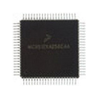
MC9S12C128VFU Freescale Semiconductor, MC9S12C128VFU Datasheet - Page 59

MC9S12C128VFU
Manufacturer Part Number
MC9S12C128VFU
Description
Manufacturer
Freescale Semiconductor
Datasheet
1.MC9S12C128VFU.pdf
(690 pages)
Specifications of MC9S12C128VFU
Cpu Family
HCS12
Device Core Size
16b
Frequency (max)
25MHz
Interface Type
CAN/SCI/SPI
Program Memory Type
Flash
Program Memory Size
128KB
Total Internal Ram Size
4KB
# I/os (max)
60
Number Of Timers - General Purpose
8
Operating Supply Voltage (typ)
2.5/5V
Operating Supply Voltage (max)
2.75/5.5V
Operating Supply Voltage (min)
2.35/2.97V
On-chip Adc
8-chx10-bit
Instruction Set Architecture
CISC
Operating Temp Range
-40C to 105C
Operating Temperature Classification
Industrial
Mounting
Surface Mount
Pin Count
80
Package Type
PQFP
Lead Free Status / Rohs Status
Not Compliant
Available stocks
Company
Part Number
Manufacturer
Quantity
Price
Company:
Part Number:
MC9S12C128VFUE
Manufacturer:
Freescale
Quantity:
38 000
Company:
Part Number:
MC9S12C128VFUE
Manufacturer:
Freescale Semiconductor
Quantity:
10 000
- Current page: 59 of 690
- Download datasheet (4Mb)
The security byte resides in a portion of the Flash array.
Check the Flash Block User Guide for more details on the security configuration.
1.5.2.2
1.5.2.2.1
This will be the most common usage of the secured part. Everything will appear the same as if the part was
not secured with the exception of BDM operation. The BDM operation will be blocked.
1.5.2.2.2
The user may wish to execute from external space with a secured microcontroller. This is accomplished
by resetting directly into expanded mode. The internal FLASH will be disabled. BDM operations will be
blocked.
1.5.2.3
In order to unsecure the microcontroller, the internal FLASH must be erased. This can be done through an
external program in expanded mode or via a sequence of BDM commands. Unsecuring is also possible via
the Backdoor Key Access. Refer to Flash Block Guide for details.
Once the user has erased the FLASH, the part can be reset into special single chip mode. This invokes a
program that verifies the erasure of the internal FLASH. Once this program completes, the user can erase
and program the FLASH security bits to the unsecured state. This is generally done through the BDM, but
the user could also change to expanded mode (by writing the mode bits through the BDM) and jumping to
an external program (again through BDM commands). Note that if the part goes through a reset before the
security bits are reprogrammed to the unsecure state, the part will be secured again.
1.5.3
The microcontroller features three main low power modes. Consult the respective Block User Guide for
information on the module behavior in stop, pseudo stop, and wait mode. An important source of
information about the clock system is the Clock and Reset Generator User Guide (CRG).
1.5.3.1
Executing the CPU STOP instruction stops all clocks and the oscillator thus putting the chip in fully static
mode. Wake up from this mode can be done via reset or external interrupts.
1.5.3.2
This mode is entered by executing the CPU STOP instruction. In this mode the oscillator is still running
and the real time interrupt (RTI) or watchdog (COP) sub module can stay active. Other peripherals are
turned off. This mode consumes more current than the full stop mode, but the wake up time from this mode
is significantly shorter.
Freescale Semiconductor
Low-Power Modes
Operation of the Secured Microcontroller
Unsecuring the Microcontroller
Stop
Pseudo Stop
Normal Single Chip Mode
Executing from External Memory
MC9S12C-Family / MC9S12GC-Family
Rev 01.24
Chapter 1 MC9S12C and MC9S12GC Device Overview (MC9S12C128)
59
Related parts for MC9S12C128VFU
Image
Part Number
Description
Manufacturer
Datasheet
Request
R
Part Number:
Description:
Manufacturer:
Freescale Semiconductor, Inc
Datasheet:
Part Number:
Description:
Manufacturer:
Freescale Semiconductor, Inc
Datasheet:
Part Number:
Description:
Manufacturer:
Freescale Semiconductor, Inc
Datasheet:
Part Number:
Description:
Manufacturer:
Freescale Semiconductor, Inc
Datasheet:
Part Number:
Description:
Manufacturer:
Freescale Semiconductor, Inc
Datasheet:
Part Number:
Description:
Manufacturer:
Freescale Semiconductor, Inc
Datasheet:
Part Number:
Description:
Manufacturer:
Freescale Semiconductor, Inc
Datasheet:
Part Number:
Description:
Manufacturer:
Freescale Semiconductor, Inc
Datasheet:
Part Number:
Description:
Manufacturer:
Freescale Semiconductor, Inc
Datasheet:
Part Number:
Description:
Manufacturer:
Freescale Semiconductor, Inc
Datasheet:
Part Number:
Description:
Manufacturer:
Freescale Semiconductor, Inc
Datasheet:
Part Number:
Description:
Manufacturer:
Freescale Semiconductor, Inc
Datasheet:
Part Number:
Description:
Manufacturer:
Freescale Semiconductor, Inc
Datasheet:
Part Number:
Description:
Manufacturer:
Freescale Semiconductor, Inc
Datasheet:
Part Number:
Description:
Manufacturer:
Freescale Semiconductor, Inc
Datasheet:


