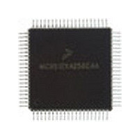
MC9S12C128VFU Freescale Semiconductor, MC9S12C128VFU Datasheet - Page 646

MC9S12C128VFU
Manufacturer Part Number
MC9S12C128VFU
Description
Manufacturer
Freescale Semiconductor
Datasheet
1.MC9S12C128VFU.pdf
(690 pages)
Specifications of MC9S12C128VFU
Cpu Family
HCS12
Device Core Size
16b
Frequency (max)
25MHz
Interface Type
CAN/SCI/SPI
Program Memory Type
Flash
Program Memory Size
128KB
Total Internal Ram Size
4KB
# I/os (max)
60
Number Of Timers - General Purpose
8
Operating Supply Voltage (typ)
2.5/5V
Operating Supply Voltage (max)
2.75/5.5V
Operating Supply Voltage (min)
2.35/2.97V
On-chip Adc
8-chx10-bit
Instruction Set Architecture
CISC
Operating Temp Range
-40C to 105C
Operating Temperature Classification
Industrial
Mounting
Surface Mount
Pin Count
80
Package Type
PQFP
Lead Free Status / Rohs Status
Not Compliant
Available stocks
Company
Part Number
Manufacturer
Quantity
Price
Company:
Part Number:
MC9S12C128VFUE
Manufacturer:
Freescale
Quantity:
38 000
Company:
Part Number:
MC9S12C128VFUE
Manufacturer:
Freescale Semiconductor
Quantity:
10 000
- Current page: 646 of 690
- Download datasheet (4Mb)
Chapter 21 128 Kbyte Flash Module (S12FTS128K1V1)
21.4.4
On each reset, the Flash module executes a reset sequence to hold CPU activity while loading the following
registers from the Flash array memory according to
21.4.4.1
If a reset occurs while any Flash command is in progress, that command will be immediately aborted. The
state of the word being programmed or the sector/array being erased is not guaranteed.
21.4.5
The Flash module can generate an interrupt when all Flash commands have completed execution or the
Flash address, data, and command buffers are empty.
21.4.5.1
Figure 21-26
The Flash module uses the CBEIF and CCIF flags in combination with the enable bits CBIE and CCIE to
discriminate for the generation of interrupts.
For a detailed description of these register bits, refer to
(FCNFG)”
646
•
•
FPROT — Flash Protection Register (see
FSEC — Flash Security Register (see
Flash Address, Data, and Command
Buffers are empty
All Flash commands have completed
execution
and
Flash Reset Sequence
Interrupts
Reset While Flash Command Active
Description of Interrupt Operation
shows the logic used for generating interrupts.
Vector addresses and their relative interrupt priority are determined at the
MCU level.
Section 21.3.2.6, “Flash Status Register
Interrupt Source
CBEIE
CBEIF
CCIE
CCIF
Figure 21-26. Flash Interrupt Implementation
Table 21-17. Flash Interrupt Sources
MC9S12C-Family / MC9S12GC-Family
Section
(FSTAT register)
(FSTAT register)
Interrupt Flag
Rev 01.24
NOTE
Section
CBEIF
CCIF
Table
21.3.2.2)
Section 21.3.2.4, “Flash Configuration Register
FLASH INTERRUPT REQUEST
(FSTAT)”.
21.3.2.5)
21-1:
Local Enable
CBEIE
CCIE
Global (CCR) Mask
Freescale Semiconductor
I Bit
I Bit
Related parts for MC9S12C128VFU
Image
Part Number
Description
Manufacturer
Datasheet
Request
R
Part Number:
Description:
Manufacturer:
Freescale Semiconductor, Inc
Datasheet:
Part Number:
Description:
Manufacturer:
Freescale Semiconductor, Inc
Datasheet:
Part Number:
Description:
Manufacturer:
Freescale Semiconductor, Inc
Datasheet:
Part Number:
Description:
Manufacturer:
Freescale Semiconductor, Inc
Datasheet:
Part Number:
Description:
Manufacturer:
Freescale Semiconductor, Inc
Datasheet:
Part Number:
Description:
Manufacturer:
Freescale Semiconductor, Inc
Datasheet:
Part Number:
Description:
Manufacturer:
Freescale Semiconductor, Inc
Datasheet:
Part Number:
Description:
Manufacturer:
Freescale Semiconductor, Inc
Datasheet:
Part Number:
Description:
Manufacturer:
Freescale Semiconductor, Inc
Datasheet:
Part Number:
Description:
Manufacturer:
Freescale Semiconductor, Inc
Datasheet:
Part Number:
Description:
Manufacturer:
Freescale Semiconductor, Inc
Datasheet:
Part Number:
Description:
Manufacturer:
Freescale Semiconductor, Inc
Datasheet:
Part Number:
Description:
Manufacturer:
Freescale Semiconductor, Inc
Datasheet:
Part Number:
Description:
Manufacturer:
Freescale Semiconductor, Inc
Datasheet:
Part Number:
Description:
Manufacturer:
Freescale Semiconductor, Inc
Datasheet:


