AD9551/PCBZ Analog Devices Inc, AD9551/PCBZ Datasheet - Page 37
AD9551/PCBZ
Manufacturer Part Number
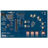
AD9551/PCBZ
Description
BOARD EVAL FOR AD9951
Manufacturer
Analog Devices Inc
Datasheet
1.AD9551PCBZ.pdf
(40 pages)
Specifications of AD9551/PCBZ
Main Purpose
Timing, Clock Generator
Embedded
No
Utilized Ic / Part
AD9551
Primary Attributes
2 Inputs, 2 Outputs, VCO
Secondary Attributes
Graphical User Interface, USB Interface
Silicon Manufacturer
Analog Devices
Application Sub Type
Clock Generator
Kit Application Type
Clock & Timing
Silicon Core Number
AD9551
Kit Contents
Board
Lead Free Status / RoHS Status
Lead free / RoHS Compliant


REFB Frequency Control (Register 0x26 to Register 0x2D)
Table 30.
Address
0x26
0x27
0x28
0x29
0x2A
0x2B
0x2C
0x2D
REFA Delay Control (Register 0x2E and Register 0x2F)
Table 31.
Address
0x2E
0x2F
REFB Delay Control (Register 0x30 and Register 0x31)
Table 32.
Address
0x30
0x31
Bit
7
6
5
4
[3:0]
[7:0]
[7:0]
[7:4]
[3:0]
[7:2]
[1:0]
7
[6:0]
[7:0]
[7:4]
[3:0]
Bit
7
[6:0]
[7:6]
[5:0]
Bit
7
[6:0]
[7:6]
[5:0]
Enable SPI control of
REFB SDM
Bypass REFB SDM
Enable REFB SDM
Enable REFA
Unused
FRACB
FRACB
FRACB
Unused
NB
Unused
Unused
MODB
MODB
MODB
Unused
Enable SPI control of REFA
delay
REFA delay control
REFA delay control
Unused
Enable SPI control of REFB
delay
REFB delay control
REFB delay control
Unused
Bit Name
Bit Name
Bit Name
Bits[8:2] of the 9-bit REFA delay word.
Bits[1:0] of the 9-bit REFA delay word.
Default is 1 0000 0000. Delay granularity is ~150 ps.
This bit must be programmed to 0, even though the default value is 1.
Description
Controls REFB frequency division functionality.
0 = REFB frequency division defined by the B[3:0] pins (default).
1 = contents of Register 0x27 to Register 0x2D define REFB frequency division via NB,
MODB, and FRACB.
Controls bypassing of the REFB SDM.
0 = allow integer-plus-fractional division (default).
1 = allow integer division only.
Controls REFB SDM enable and hold functionality.
0 = reset REFB SDM and stop its clocks.
1 = REFB SDM enabled (default).
Controls REFA enable and power-down functionality.
0 = power down REFA input receiver (ineffective unless Register 0x1A[1] = 1).
1 = normal operation (default).
Unused.
Bits[19:12] of the 20-bit fractional part of the REFB SDM.
Bits[11:4] of the 20-bit fractional part of the REFB SDM.
Bits[3:0] of the 20-bit fractional part of the REFB SDM.
Default is FRACB = 0100 0000 0000 0000 0000 (262,144).
Note that FRACB assumes twos complement format.
Unused.
6-bit integer divide value for the REFB SDM. Default divide value is 8.
Unused.
Bits[18:12] of the 19-bit modulus of the REFB SDM.
Bits[11:4] of the 19-bit modulus of the REFB SDM.
Bits[3:0] of the 19-bit modulus of the REFB SDM.
Default is MODB = 000 0000 0000 0000 0000.
Unused.
Description
Controls REFA delay functionality.
0 = the device automatically selects REFA delay (default).
1 = REFA delay defined by Register 0x2E[6:0] and Register 0x2F[7:6].
Unused.
Description
Controls REFB delay functionality:
0 = the device automatically selects REFB delay (default).
1 = REFB delay defined by Register 0x30[6:0] and Register 0x31[7:6].
Bits[8:2] of the 9-bit REFB delay word.
Bits[1:0] of the 9-bit REFB delay word.
Default is 1 0000 0000. Delay granularity is ~150 ps.
Unused.
Rev. B | Page 37 of 40
AD9551
Related parts for AD9551/PCBZ
Image
Part Number
Description
Manufacturer
Datasheet
Request
R


Part Number:
Description:
±1.7g Dual-Axis IMEMS Accelerometer Evaluation Board
Manufacturer:
Analog Devices Inc
Datasheet:

Part Number:
Description:
Inertial Sensor Evaluation System
Manufacturer:
Analog Devices Inc
Datasheet:
Part Number:
Description:
Manufacturer:
Analog Devices Inc
Datasheet:
Part Number:
Description:
Manufacturer:
Analog Devices Inc
Datasheet:
Part Number:
Description:
Manufacturer:
Analog Devices Inc
Datasheet:
Part Number:
Description:
Manufacturer:
Analog Devices Inc
Datasheet:
Part Number:
Description:
Manufacturer:
Analog Devices Inc
Datasheet:
Part Number:
Description:
Manufacturer:
Analog Devices Inc
Datasheet:
Part Number:
Description:
Manufacturer:
Analog Devices Inc
Datasheet:
Part Number:
Description:
Manufacturer:
Analog Devices Inc
Datasheet:
Part Number:
Description:
Manufacturer:
Analog Devices Inc
Datasheet:
Part Number:
Description:
Manufacturer:
Analog Devices Inc
Datasheet: