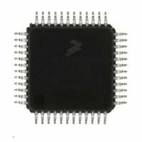
MC9S08DV32ACLF Freescale Semiconductor, MC9S08DV32ACLF Datasheet - Page 114

MC9S08DV32ACLF
Manufacturer Part Number
MC9S08DV32ACLF
Description
IC MCU 32K FLASH 2K RAM 48-LQFP
Manufacturer
Freescale Semiconductor
Series
HCS08r
Specifications of MC9S08DV32ACLF
Core Processor
HCS08
Core Size
8-Bit
Speed
40MHz
Connectivity
CAN, I²C, LIN, SCI, SPI
Peripherals
LVD, POR, PWM, WDT
Number Of I /o
39
Program Memory Size
32KB (32K x 8)
Program Memory Type
FLASH
Ram Size
2K x 8
Voltage - Supply (vcc/vdd)
2.7 V ~ 5.5 V
Data Converters
A/D 16x12b
Oscillator Type
External
Operating Temperature
-40°C ~ 85°C
Package / Case
48-LQFP
Processor Series
S08DV
Core
HCS08
Data Bus Width
8 bit
Data Ram Size
2 KB
Interface Type
CAN, I2C, SCI, SPI
Number Of Programmable I/os
26
Operating Supply Voltage
5.5 V
Mounting Style
SMD/SMT
3rd Party Development Tools
EWS08
Development Tools By Supplier
DEMO9S08DZ60
On-chip Adc
12 bit, 10 channel
Controller Family/series
HCS08
No. Of I/o's
39
Ram Memory Size
2KB
Cpu Speed
40MHz
No. Of Timers
2
Digital Ic Case Style
LQFP
Rohs Compliant
Yes
Lead Free Status / RoHS Status
Lead free / RoHS Compliant
Eeprom Size
-
Lead Free Status / Rohs Status
Lead free / RoHS Compliant
Available stocks
Company
Part Number
Manufacturer
Quantity
Price
Company:
Part Number:
MC9S08DV32ACLF
Manufacturer:
Freescale Semiconductor
Quantity:
10 000
- Current page: 114 of 414
- Download datasheet (5Mb)
Chapter 7 Central Processor Unit (S08CPUV3)
7.2
Figure 7-1
7.2.1
The A accumulator is a general-purpose 8-bit register. One operand input to the arithmetic logic unit
(ALU) is connected to the accumulator and the ALU results are often stored into the A accumulator after
arithmetic and logical operations. The accumulator can be loaded from memory using various addressing
modes to specify the address where the loaded data comes from, or the contents of A can be stored to
memory using various addressing modes to specify the address where data from A will be stored.
Reset has no effect on the contents of the A accumulator.
7.2.2
This 16-bit register is actually two separate 8-bit registers (H and X), which often work together as a 16-bit
address pointer where H holds the upper byte of an address and X holds the lower byte of the address. All
indexed addressing mode instructions use the full 16-bit value in H:X as an index reference pointer;
however, for compatibility with the earlier M68HC05 Family, some instructions operate only on the
low-order 8-bit half (X).
Many instructions treat X as a second general-purpose 8-bit register that can be used to hold 8-bit data
values. X can be cleared, incremented, decremented, complemented, negated, shifted, or rotated. Transfer
instructions allow data to be transferred from A or transferred to A where arithmetic and logical operations
can then be performed.
For compatibility with the earlier M68HC05 Family, H is forced to 0x00 during reset. Reset has no effect
on the contents of X.
114
Programmer’s Model and CPU Registers
shows the five CPU registers. CPU registers are not part of the memory map.
Accumulator (A)
Index Register (H:X)
H
CONDITION CODE REGISTER
15
15
INDEX REGISTER (HIGH)
16-BIT INDEX REGISTER H:X
PROGRAM COUNTER
MC9S08DV60 Series Data Sheet, Rev 3
STACK POINTER
Figure 7-1. CPU Registers
8
V 1 1 H I N Z
7
7
7
INDEX REGISTER (LOW)
ACCUMULATOR
0
0
0
0
C
CARRY
ZERO
NEGATIVE
INTERRUPT MASK
HALF-CARRY (FROM BIT 3)
TWO’S COMPLEMENT OVERFLOW
SP
PC
CCR
A
X
Freescale Semiconductor
Related parts for MC9S08DV32ACLF
Image
Part Number
Description
Manufacturer
Datasheet
Request
R
Part Number:
Description:
Manufacturer:
Freescale Semiconductor, Inc
Datasheet:
Part Number:
Description:
Manufacturer:
Freescale Semiconductor, Inc
Datasheet:
Part Number:
Description:
Manufacturer:
Freescale Semiconductor, Inc
Datasheet:
Part Number:
Description:
Manufacturer:
Freescale Semiconductor, Inc
Datasheet:
Part Number:
Description:
Manufacturer:
Freescale Semiconductor, Inc
Datasheet:
Part Number:
Description:
Manufacturer:
Freescale Semiconductor, Inc
Datasheet:
Part Number:
Description:
Manufacturer:
Freescale Semiconductor, Inc
Datasheet:
Part Number:
Description:
Manufacturer:
Freescale Semiconductor, Inc
Datasheet:
Part Number:
Description:
Manufacturer:
Freescale Semiconductor, Inc
Datasheet:
Part Number:
Description:
Manufacturer:
Freescale Semiconductor, Inc
Datasheet:
Part Number:
Description:
Manufacturer:
Freescale Semiconductor, Inc
Datasheet:
Part Number:
Description:
Manufacturer:
Freescale Semiconductor, Inc
Datasheet:
Part Number:
Description:
Manufacturer:
Freescale Semiconductor, Inc
Datasheet:
Part Number:
Description:
Manufacturer:
Freescale Semiconductor, Inc
Datasheet:
Part Number:
Description:
Manufacturer:
Freescale Semiconductor, Inc
Datasheet:


