MC9S08DV32ACLF Freescale Semiconductor, MC9S08DV32ACLF Datasheet - Page 359
MC9S08DV32ACLF
Manufacturer Part Number
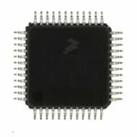
MC9S08DV32ACLF
Description
IC MCU 32K FLASH 2K RAM 48-LQFP
Manufacturer
Freescale Semiconductor
Series
HCS08r
Specifications of MC9S08DV32ACLF
Core Processor
HCS08
Core Size
8-Bit
Speed
40MHz
Connectivity
CAN, I²C, LIN, SCI, SPI
Peripherals
LVD, POR, PWM, WDT
Number Of I /o
39
Program Memory Size
32KB (32K x 8)
Program Memory Type
FLASH
Ram Size
2K x 8
Voltage - Supply (vcc/vdd)
2.7 V ~ 5.5 V
Data Converters
A/D 16x12b
Oscillator Type
External
Operating Temperature
-40°C ~ 85°C
Package / Case
48-LQFP
Processor Series
S08DV
Core
HCS08
Data Bus Width
8 bit
Data Ram Size
2 KB
Interface Type
CAN, I2C, SCI, SPI
Number Of Programmable I/os
26
Operating Supply Voltage
5.5 V
Mounting Style
SMD/SMT
3rd Party Development Tools
EWS08
Development Tools By Supplier
DEMO9S08DZ60
On-chip Adc
12 bit, 10 channel
Controller Family/series
HCS08
No. Of I/o's
39
Ram Memory Size
2KB
Cpu Speed
40MHz
No. Of Timers
2
Digital Ic Case Style
LQFP
Rohs Compliant
Yes
Lead Free Status / RoHS Status
Lead free / RoHS Compliant
Eeprom Size
-
Lead Free Status / Rohs Status
Lead free / RoHS Compliant
Available stocks
Company
Part Number
Manufacturer
Quantity
Price

Company:
Part Number:
MC9S08DV32ACLF
Manufacturer:
Freescale Semiconductor
Quantity:
10 000


17.3.6
The BRKEN control bit in the DBGC register may be set to 1 to allow any of the trigger conditions
described in
CPU. TAG in DBGC controls whether the breakpoint request will be treated as a tag-type breakpoint or a
force-type breakpoint. A tag breakpoint causes the current opcode to be marked as it enters the instruction
queue. If a tagged opcode reaches the end of the pipe, the CPU executes a BGND instruction to go to active
background mode rather than executing the tagged opcode. A force-type breakpoint causes the CPU to
finish the current instruction and then go to active background mode.
If the background mode has not been enabled (ENBDM = 1) by a serial WRITE_CONTROL command
through the BKGD pin, the CPU will execute an SWI instruction instead of going to active background
mode.
17.4
This section contains the descriptions of the BDC and DBG registers and control bits.
Refer to the high-page register summary in the device overview chapter of this data sheet for the absolute
address assignments for all DBG registers. This section refers to registers and control bits only by their
names. A Freescale-provided equate or header file is used to translate these names into the appropriate
absolute addresses.
17.4.1
The BDC has two registers:
These registers are accessed with dedicated serial BDC commands and are not located in the memory
space of the target MCU (so they do not have addresses and cannot be accessed by user programs).
Some of the bits in the BDCSCR have write limitations; otherwise, these registers may be read or written
at any time. For example, the ENBDM control bit may not be written while the MCU is in active
background mode. (This prevents the ambiguous condition of the control bit forbidding active background
mode while the MCU is already in active background mode.) Also, the four status bits (BDMACT, WS,
WSF, and DVF) are read-only status indicators and can never be written by the WRITE_CONTROL serial
BDC command. The clock switch (CLKSW) control bit may be read or written at any time.
Freescale Semiconductor
•
•
The BDC status and control register (BDCSCR) is an 8-bit register containing control and status
bits for the background debug controller.
The BDC breakpoint match register (BDCBKPT) holds a 16-bit breakpoint match address.
Register Definition
Hardware Breakpoints
BDC Registers and Control Bits
Section 17.3.5, “Trigger
MC9S08DV60 Series Data Sheet, Rev 3
Modes,”
to be used to generate a hardware breakpoint request to the
Chapter 17 Development Support
359
Related parts for MC9S08DV32ACLF
Image
Part Number
Description
Manufacturer
Datasheet
Request
R

Part Number:
Description:
Manufacturer:
Freescale Semiconductor, Inc
Datasheet:
Part Number:
Description:
Manufacturer:
Freescale Semiconductor, Inc
Datasheet:
Part Number:
Description:
Manufacturer:
Freescale Semiconductor, Inc
Datasheet:
Part Number:
Description:
Manufacturer:
Freescale Semiconductor, Inc
Datasheet:
Part Number:
Description:
Manufacturer:
Freescale Semiconductor, Inc
Datasheet:
Part Number:
Description:
Manufacturer:
Freescale Semiconductor, Inc
Datasheet:
Part Number:
Description:
Manufacturer:
Freescale Semiconductor, Inc
Datasheet:
Part Number:
Description:
Manufacturer:
Freescale Semiconductor, Inc
Datasheet:
Part Number:
Description:
Manufacturer:
Freescale Semiconductor, Inc
Datasheet:
Part Number:
Description:
Manufacturer:
Freescale Semiconductor, Inc
Datasheet:
Part Number:
Description:
Manufacturer:
Freescale Semiconductor, Inc
Datasheet:
Part Number:
Description:
Manufacturer:
Freescale Semiconductor, Inc
Datasheet:
Part Number:
Description:
Manufacturer:
Freescale Semiconductor, Inc
Datasheet:
Part Number:
Description:
Manufacturer:
Freescale Semiconductor, Inc
Datasheet:
Part Number:
Description:
Manufacturer:
Freescale Semiconductor, Inc
Datasheet: