MC9S08DV32ACLF Freescale Semiconductor, MC9S08DV32ACLF Datasheet - Page 172
MC9S08DV32ACLF
Manufacturer Part Number
MC9S08DV32ACLF
Description
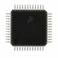
IC MCU 32K FLASH 2K RAM 48-LQFP
Manufacturer
Freescale Semiconductor
Series
HCS08r
Specifications of MC9S08DV32ACLF
Core Processor
HCS08
Core Size
8-Bit
Speed
40MHz
Connectivity
CAN, I²C, LIN, SCI, SPI
Peripherals
LVD, POR, PWM, WDT
Number Of I /o
39
Program Memory Size
32KB (32K x 8)
Program Memory Type
FLASH
Ram Size
2K x 8
Voltage - Supply (vcc/vdd)
2.7 V ~ 5.5 V
Data Converters
A/D 16x12b
Oscillator Type
External
Operating Temperature
-40°C ~ 85°C
Package / Case
48-LQFP
Processor Series
S08DV
Core
HCS08
Data Bus Width
8 bit
Data Ram Size
2 KB
Interface Type
CAN, I2C, SCI, SPI
Number Of Programmable I/os
26
Operating Supply Voltage
5.5 V
Mounting Style
SMD/SMT
3rd Party Development Tools
EWS08
Development Tools By Supplier
DEMO9S08DZ60
On-chip Adc
12 bit, 10 channel
Controller Family/series
HCS08
No. Of I/o's
39
Ram Memory Size
2KB
Cpu Speed
40MHz
No. Of Timers
2
Digital Ic Case Style
LQFP
Rohs Compliant
Yes
Lead Free Status / RoHS Status
Lead free / RoHS Compliant
Eeprom Size
-
Lead Free Status / Rohs Status
Lead free / RoHS Compliant
Available stocks
Company
Part Number
Manufacturer
Quantity
Price

Company:
Part Number:
MC9S08DV32ACLF
Manufacturer:
Freescale Semiconductor
Quantity:
10 000


Chapter 10 Analog-to-Digital Converter (S08ADC12V1)
10.1.3
The ADC module is capable of performing conversions using the MCU bus clock, the bus clock divided
by two, the local asynchronous clock (ADACK) within the module, or the alternate clock, ALTCLK. The
alternate clock for the MC9S08DV60 Series MCU devices is the external reference clock (MCGERCLK).
The selected clock source must run at a frequency such that the ADC conversion clock (ADCK) runs at a
frequency within its specified range (f
determined by the ADIV bits.
ALTCLK is active while the MCU is in wait mode provided the conditions described above are met. This
allows ALTCLK to be used as the conversion clock source for the ADC while the MCU is in wait mode.
ALTCLK cannot be used as the ADC conversion clock source while the MCU is in either stop2 or stop3.
10.1.4
The ADC hardware trigger, ADHWT, is the output from the real time counter (RTC). The RTC counter
can be clocked by either MCGERCLK or a nominal 1 kHz clock source.
The period of the RTC is determined by the input clock frequency, the RTCPS bits, and the RTCMOD
register. When the ADC hardware trigger is enabled, a conversion is initiated upon an RTC counter
overflow.
The RTC can be configured to cause a hardware trigger in MCU run, wait, and stop3.
172
Notes:
ADCH
00000
00001
00010
00011
00100
00101
00110
00111
01000
01001
01010
01011
1 For information, see
Alternate Clock
Hardware Trigger
Channel
AD10
AD11
AD0
AD1
AD2
AD3
AD4
AD5
AD6
AD7
AD8
AD9
Section 10.1.5, “Temperature
PTA2/ADP2/ACMP1P-
PTA3/ADP3/ACMP1O
PTA1/ADP1/ACMP1+
PTA0/ADP0/MCLK
Table 10-1. ADC Channel Assignment
PTB2/ADP10
PTB3/ADP11
PTB0/ADP8
PTB1/ADP9
PTA4/ADP4
PTA5/ADP5
PTA6/ADP6
PTA7/ADP7
MC9S08DV60 Series Data Sheet, Rev 3
Input
ADCK
) after being divided down from the ALTCLK input as
Sensor”.
10000–
ADCH
01100
01101
01110
01111
11001
11010
11011
11100
11101
11110
11111
AD16 through AD25
Module Disabled
Reserved
Channel
V
V
AD12
AD13
AD14
AD15
AD26
AD27
REFH
REFL
Freescale Semiconductor
Temperature Sensor
Internal Bandgap
PTB4/ADP12
PTB5/ADP13
PTB6/ADP14
PTB7/ADP15
Reserved
Reserved
V
V
Input
None
REFH
REFL
2
1
Related parts for MC9S08DV32ACLF
Image
Part Number
Description
Manufacturer
Datasheet
Request
R

Part Number:
Description:
Manufacturer:
Freescale Semiconductor, Inc
Datasheet:
Part Number:
Description:
Manufacturer:
Freescale Semiconductor, Inc
Datasheet:
Part Number:
Description:
Manufacturer:
Freescale Semiconductor, Inc
Datasheet:
Part Number:
Description:
Manufacturer:
Freescale Semiconductor, Inc
Datasheet:
Part Number:
Description:
Manufacturer:
Freescale Semiconductor, Inc
Datasheet:
Part Number:
Description:
Manufacturer:
Freescale Semiconductor, Inc
Datasheet:
Part Number:
Description:
Manufacturer:
Freescale Semiconductor, Inc
Datasheet:
Part Number:
Description:
Manufacturer:
Freescale Semiconductor, Inc
Datasheet:
Part Number:
Description:
Manufacturer:
Freescale Semiconductor, Inc
Datasheet:
Part Number:
Description:
Manufacturer:
Freescale Semiconductor, Inc
Datasheet:
Part Number:
Description:
Manufacturer:
Freescale Semiconductor, Inc
Datasheet:
Part Number:
Description:
Manufacturer:
Freescale Semiconductor, Inc
Datasheet:
Part Number:
Description:
Manufacturer:
Freescale Semiconductor, Inc
Datasheet:
Part Number:
Description:
Manufacturer:
Freescale Semiconductor, Inc
Datasheet:
Part Number:
Description:
Manufacturer:
Freescale Semiconductor, Inc
Datasheet: