MC9S08DV32ACLF Freescale Semiconductor, MC9S08DV32ACLF Datasheet - Page 211
MC9S08DV32ACLF
Manufacturer Part Number
MC9S08DV32ACLF
Description
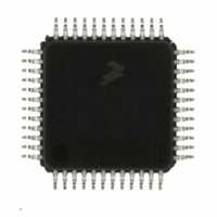
IC MCU 32K FLASH 2K RAM 48-LQFP
Manufacturer
Freescale Semiconductor
Series
HCS08r
Specifications of MC9S08DV32ACLF
Core Processor
HCS08
Core Size
8-Bit
Speed
40MHz
Connectivity
CAN, I²C, LIN, SCI, SPI
Peripherals
LVD, POR, PWM, WDT
Number Of I /o
39
Program Memory Size
32KB (32K x 8)
Program Memory Type
FLASH
Ram Size
2K x 8
Voltage - Supply (vcc/vdd)
2.7 V ~ 5.5 V
Data Converters
A/D 16x12b
Oscillator Type
External
Operating Temperature
-40°C ~ 85°C
Package / Case
48-LQFP
Processor Series
S08DV
Core
HCS08
Data Bus Width
8 bit
Data Ram Size
2 KB
Interface Type
CAN, I2C, SCI, SPI
Number Of Programmable I/os
26
Operating Supply Voltage
5.5 V
Mounting Style
SMD/SMT
3rd Party Development Tools
EWS08
Development Tools By Supplier
DEMO9S08DZ60
On-chip Adc
12 bit, 10 channel
Controller Family/series
HCS08
No. Of I/o's
39
Ram Memory Size
2KB
Cpu Speed
40MHz
No. Of Timers
2
Digital Ic Case Style
LQFP
Rohs Compliant
Yes
Lead Free Status / RoHS Status
Lead free / RoHS Compliant
Eeprom Size
-
Lead Free Status / Rohs Status
Lead free / RoHS Compliant
Available stocks
Company
Part Number
Manufacturer
Quantity
Price

Company:
Part Number:
MC9S08DV32ACLF
Manufacturer:
Freescale Semiconductor
Quantity:
10 000


11.4.2
For 10-bit addressing, 0x11110 is used for the first 5 bits of the first address byte. Various combinations of
read/write formats are possible within a transfer that includes 10-bit addressing.
11.4.2.1
The transfer direction is not changed (see
each slave compares the first seven bits of the first byte of the slave address (11110XX) with its own
address and tests whether the eighth bit (R/W direction bit) is 0. More than one device can find a match
and generate an acknowledge (A1). Then, each slave that finds a match compares the eight bits of the
second byte of the slave address with its own address. Only one slave finds a match and generates an
acknowledge (A2). The matching slave remains addressed by the master until it receives a stop condition
(P) or a repeated start condition (Sr) followed by a different slave address.
After the master-transmitter has sent the first byte of the 10-bit address, the slave-receiver sees an IIC
interrupt. Software must ensure the contents of IICD are ignored and not treated as valid data for this
interrupt.
11.4.2.2
The transfer direction is changed after the second R/W bit (see
acknowledge bit A2, the procedure is the same as that described for a master-transmitter addressing a
slave-receiver. After the repeated start condition (Sr), a matching slave remembers that it was addressed
before. This slave then checks whether the first seven bits of the first byte of the slave address following
Sr are the same as they were after the start condition (S) and tests whether the eighth (R/W) bit is 1. If there
is a match, the slave considers that it has been addressed as a transmitter and generates acknowledge A3.
The slave-transmitter remains addressed until it receives a stop condition (P) or a repeated start condition
(Sr) followed by a different slave address.
After a repeated start condition (Sr), all other slave devices also compare the first seven bits of the first byte
of the slave address with their own addresses and test the eighth (R/W) bit. However, none of them are
addressed because R/W = 1 (for 10-bit devices) or the 11110XX slave address (for 7-bit devices) does not
match.
After the master-receiver has sent the first byte of the 10-bit address, the slave-transmitter sees an IIC
interrupt. Software must ensure the contents of IICD are ignored and not treated as valid data for this
interrupt.
Freescale Semiconductor
S
11110 + AD10 + AD9
Slave Address
1st 7 bits
S
10-bit Address
Table 11-10. Master-Receiver Addresses a Slave-Transmitter with a 10-bit Address
Slave Address 1st 7 bits
Master-Transmitter Addresses a Slave-Receiver
Table 11-9. Master-Transmitter Addresses Slave-Receiver with a 10-bit Address
Master-Receiver Addresses a Slave-Transmitter
11110 + AD10 + AD9
R/W
0
A1
Slave Address
R/W
2nd byte
AD[8:1]
0
MC9S08DV60 Series Data Sheet, Rev 3
A1
Table
Slave Address 2nd byte
A2
11-9). When a 10-bit address follows a start condition,
Sr
AD[8:1]
11110 + AD10 + AD9
Slave Address
1st 7 bits
Table
A2
Data
Chapter 11 Inter-Integrated Circuit (S08IICV2)
11-10). Up to and including
R/W
1
A
A3
...
Data
Data
A
A/A
...
Data
P
A
211
P
Related parts for MC9S08DV32ACLF
Image
Part Number
Description
Manufacturer
Datasheet
Request
R

Part Number:
Description:
Manufacturer:
Freescale Semiconductor, Inc
Datasheet:
Part Number:
Description:
Manufacturer:
Freescale Semiconductor, Inc
Datasheet:
Part Number:
Description:
Manufacturer:
Freescale Semiconductor, Inc
Datasheet:
Part Number:
Description:
Manufacturer:
Freescale Semiconductor, Inc
Datasheet:
Part Number:
Description:
Manufacturer:
Freescale Semiconductor, Inc
Datasheet:
Part Number:
Description:
Manufacturer:
Freescale Semiconductor, Inc
Datasheet:
Part Number:
Description:
Manufacturer:
Freescale Semiconductor, Inc
Datasheet:
Part Number:
Description:
Manufacturer:
Freescale Semiconductor, Inc
Datasheet:
Part Number:
Description:
Manufacturer:
Freescale Semiconductor, Inc
Datasheet:
Part Number:
Description:
Manufacturer:
Freescale Semiconductor, Inc
Datasheet:
Part Number:
Description:
Manufacturer:
Freescale Semiconductor, Inc
Datasheet:
Part Number:
Description:
Manufacturer:
Freescale Semiconductor, Inc
Datasheet:
Part Number:
Description:
Manufacturer:
Freescale Semiconductor, Inc
Datasheet:
Part Number:
Description:
Manufacturer:
Freescale Semiconductor, Inc
Datasheet:
Part Number:
Description:
Manufacturer:
Freescale Semiconductor, Inc
Datasheet: