MC9S08DV32ACLF Freescale Semiconductor, MC9S08DV32ACLF Datasheet - Page 78
MC9S08DV32ACLF
Manufacturer Part Number
MC9S08DV32ACLF
Description
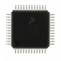
IC MCU 32K FLASH 2K RAM 48-LQFP
Manufacturer
Freescale Semiconductor
Series
HCS08r
Specifications of MC9S08DV32ACLF
Core Processor
HCS08
Core Size
8-Bit
Speed
40MHz
Connectivity
CAN, I²C, LIN, SCI, SPI
Peripherals
LVD, POR, PWM, WDT
Number Of I /o
39
Program Memory Size
32KB (32K x 8)
Program Memory Type
FLASH
Ram Size
2K x 8
Voltage - Supply (vcc/vdd)
2.7 V ~ 5.5 V
Data Converters
A/D 16x12b
Oscillator Type
External
Operating Temperature
-40°C ~ 85°C
Package / Case
48-LQFP
Processor Series
S08DV
Core
HCS08
Data Bus Width
8 bit
Data Ram Size
2 KB
Interface Type
CAN, I2C, SCI, SPI
Number Of Programmable I/os
26
Operating Supply Voltage
5.5 V
Mounting Style
SMD/SMT
3rd Party Development Tools
EWS08
Development Tools By Supplier
DEMO9S08DZ60
On-chip Adc
12 bit, 10 channel
Controller Family/series
HCS08
No. Of I/o's
39
Ram Memory Size
2KB
Cpu Speed
40MHz
No. Of Timers
2
Digital Ic Case Style
LQFP
Rohs Compliant
Yes
Lead Free Status / RoHS Status
Lead free / RoHS Compliant
Eeprom Size
-
Lead Free Status / Rohs Status
Lead free / RoHS Compliant
Available stocks
Company
Part Number
Manufacturer
Quantity
Price

Company:
Part Number:
MC9S08DV32ACLF
Manufacturer:
Freescale Semiconductor
Quantity:
10 000


1
2
Chapter 5 Resets, Interrupts, and General System Control
5.8.4
This high page register is a write-once register so only the first write after reset is honored. It can be read
at any time. Any subsequent attempt to write to SOPT1 (intentionally or unintentionally) is ignored to
avoid accidental changes to these sensitive settings. This register should be written during the user’s reset
initialization program to set the desired controls even if the desired settings are the same as the reset
settings.
78
COPT[1:0]
Windowed COP operation requires the user to clear the COP timer in the last 25% of the selected timeout period. This column
displays the minimum number of clock counts required before the COP timer can be reset when in windowed COP mode
(COPW = 1).
Values shown in milliseconds based on t
tolerance of this value.
Reset:
SCI2PS
STOPE
COPCLKS
IICPS
Field
7:6
5
4
3
W
N/A
R
0
0
0
1
1
1
Control Bits
System Options Register 1 (SOPT1)
COP Watchdog Timeout — These write-once bits select the timeout period of the COP. COPT along with
COPCLKS in SOPT2 defines the COP timeout period. See
Stop Mode Enable — This write-once bit is used to enable stop mode. If stop mode is disabled and a user
program attempts to execute a STOP instruction, an illegal opcode reset is forced.
0 Stop mode disabled.
1 Stop mode enabled.
SCI2 Pin Select— This write-once bit selects the location of the RxD2 and TxD2 pins of the SCI2 module.
0 TxD2 on PTF0, RxD2 on PTF1.
1 TxD2 on PTE6, RxD2 on PTE7.
IIC Pin Select— This write-once bit selects the location of the SCL and SDA pins of the IIC module.
0 SCL on PTF2, SDA on PTF3.
1 SCL on PTE4, SDA on PTE5.
1
7
COPT
COPT[1:0]
= Unimplemented or Reserved
0:0
0:1
1:0
1:1
0:1
1:0
1:1
1
6
Figure 5-5. System Options Register 1 (SOPT1)
Table 5-5. SOPT1 Register Field Descriptions
Clock Source
Table 5-6. COP Configuration Options
LPO
STOPE
MC9S08DV60 Series Data Sheet, Rev 3
1 kHz
1 kHz
1 kHz
0
N/A
Bus
Bus
Bus
5
= 1 ms. See t
SCI2PS
COP Window
LPO
0
4
196,608 cycles
49,152 cycles
Description
(COPW = 1)
6144 cycles
in the appendix
N/A
N/A
N/A
N/A
IICPS
1
Table
Opens
3
0
5-6.
Section A.12.1, “Control
0
0
2
COP Overflow Count
2
2
2
10
8
5
COP is disabled
cycles (256 ms
cycles (32 ms
cycles (1.024 s
2
2
2
Freescale Semiconductor
13
16
18
cycles
cycles
cycles
0
0
1
Timing,” for the
2
1
1
)
)
)
0
0
0
Related parts for MC9S08DV32ACLF
Image
Part Number
Description
Manufacturer
Datasheet
Request
R

Part Number:
Description:
Manufacturer:
Freescale Semiconductor, Inc
Datasheet:
Part Number:
Description:
Manufacturer:
Freescale Semiconductor, Inc
Datasheet:
Part Number:
Description:
Manufacturer:
Freescale Semiconductor, Inc
Datasheet:
Part Number:
Description:
Manufacturer:
Freescale Semiconductor, Inc
Datasheet:
Part Number:
Description:
Manufacturer:
Freescale Semiconductor, Inc
Datasheet:
Part Number:
Description:
Manufacturer:
Freescale Semiconductor, Inc
Datasheet:
Part Number:
Description:
Manufacturer:
Freescale Semiconductor, Inc
Datasheet:
Part Number:
Description:
Manufacturer:
Freescale Semiconductor, Inc
Datasheet:
Part Number:
Description:
Manufacturer:
Freescale Semiconductor, Inc
Datasheet:
Part Number:
Description:
Manufacturer:
Freescale Semiconductor, Inc
Datasheet:
Part Number:
Description:
Manufacturer:
Freescale Semiconductor, Inc
Datasheet:
Part Number:
Description:
Manufacturer:
Freescale Semiconductor, Inc
Datasheet:
Part Number:
Description:
Manufacturer:
Freescale Semiconductor, Inc
Datasheet:
Part Number:
Description:
Manufacturer:
Freescale Semiconductor, Inc
Datasheet:
Part Number:
Description:
Manufacturer:
Freescale Semiconductor, Inc
Datasheet: