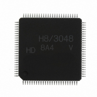
HD64F3048VTF8 Renesas Electronics America, HD64F3048VTF8 Datasheet - Page 629

HD64F3048VTF8
Manufacturer Part Number
HD64F3048VTF8
Description
IC H8 MCU FLASH 128K 100-QFP
Manufacturer
Renesas Electronics America
Series
H8® H8/300Hr
Datasheet
1.HD64F3048F16.pdf
(907 pages)
Specifications of HD64F3048VTF8
Core Processor
H8/300H
Core Size
16-Bit
Speed
8MHz
Connectivity
SCI, SmartCard
Peripherals
DMA, PWM, WDT
Number Of I /o
70
Program Memory Size
128KB (128K x 8)
Program Memory Type
FLASH
Ram Size
4K x 8
Voltage - Supply (vcc/vdd)
2.7 V ~ 5.5 V
Data Converters
A/D 8x10b; D/A 2x8b
Oscillator Type
Internal
Operating Temperature
-20°C ~ 75°C
Package / Case
100-TQFP, 100-VQFP
Lead Free Status / RoHS Status
Contains lead / RoHS non-compliant
Eeprom Size
-
Other names
HD64F3048VX8
- Current page: 629 of 907
- Download datasheet (6Mb)
User Program Mode Execution Procedure: Figure 19.7 shows the procedure for user program
mode execution in RAM.
Note: To prevent microcontroller errors caused by accidental programming or erasing, apply 12 V to
1
2
3
4
5
V
by RAM; do not apply 12 V to the V
watchdog timer should be running and enabled to halt runaway program execution, so that
program runaway will not lead to overprogramming or overerasing. For further information
about turning V
Precautions (Dual-Power Supply).
Set MD
PP
Execute user application program
Store user application programs
only when the flash memory is programmed or erased, or when flash memory is emulated
Transfer on-board update
Execute on-board update
Update flash memory
Apply 0 to 5 V to MD
2
(user program mode)
program into RAM
to MD
program in RAM
Wait 5 to 10 µs
Figure 19.7 User Program Mode Operation (Example)
Set V
V
PP
0
PP
= 12 V
to 101, 110, or 111
PP
on and off, see section 19.8, Flash Memory Programming and Erasing
Section 19 Flash Memory (H8/3048F: Dual Power Supply (V
E bit
2
PP
pin during normal operation. While 12 V is applied, the
Procedure
1. The user stores application programs in flash
2. Pin inputs are set up for user program mode.
3. A reset starts the CPU, which transfers the
4. Following a branch to the program in RAM,
5. After the on-board update ends, clear the
memory. One of these is an on-board
update program that will execute steps 3 to 5
below.
on-board update program into RAM.
the on-board update program is executed.
V
memory.
Wait 5 to 10 s to stabilize internal power
supply.
Update program is executed.
V
updated user application program and this
program is executed.
After clearing the V
memory program executes, flash memory
read setup time (t
PP
PP
Rev. 7.00 Sep 21, 2005 page 603 of 878
E bit in FLMCR is set to update flash
E bit then a branch is made to the
FRS
PP
) is needed.
E bit, before the flash
REJ09B0259-0700
PP
= 12 V))
Related parts for HD64F3048VTF8
Image
Part Number
Description
Manufacturer
Datasheet
Request
R

Part Number:
Description:
KIT STARTER FOR M16C/29
Manufacturer:
Renesas Electronics America
Datasheet:

Part Number:
Description:
KIT STARTER FOR R8C/2D
Manufacturer:
Renesas Electronics America
Datasheet:

Part Number:
Description:
R0K33062P STARTER KIT
Manufacturer:
Renesas Electronics America
Datasheet:

Part Number:
Description:
KIT STARTER FOR R8C/23 E8A
Manufacturer:
Renesas Electronics America
Datasheet:

Part Number:
Description:
KIT STARTER FOR R8C/25
Manufacturer:
Renesas Electronics America
Datasheet:

Part Number:
Description:
KIT STARTER H8S2456 SHARPE DSPLY
Manufacturer:
Renesas Electronics America
Datasheet:

Part Number:
Description:
KIT STARTER FOR R8C38C
Manufacturer:
Renesas Electronics America
Datasheet:

Part Number:
Description:
KIT STARTER FOR R8C35C
Manufacturer:
Renesas Electronics America
Datasheet:

Part Number:
Description:
KIT STARTER FOR R8CL3AC+LCD APPS
Manufacturer:
Renesas Electronics America
Datasheet:

Part Number:
Description:
KIT STARTER FOR RX610
Manufacturer:
Renesas Electronics America
Datasheet:

Part Number:
Description:
KIT STARTER FOR R32C/118
Manufacturer:
Renesas Electronics America
Datasheet:

Part Number:
Description:
KIT DEV RSK-R8C/26-29
Manufacturer:
Renesas Electronics America
Datasheet:

Part Number:
Description:
KIT STARTER FOR SH7124
Manufacturer:
Renesas Electronics America
Datasheet:

Part Number:
Description:
KIT STARTER FOR H8SX/1622
Manufacturer:
Renesas Electronics America
Datasheet:


