MRF24J40-I/ML Microchip Technology, MRF24J40-I/ML Datasheet - Page 100
MRF24J40-I/ML
Manufacturer Part Number
MRF24J40-I/ML
Description
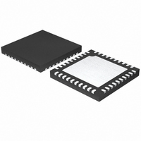
IC TXRX IEEE/ZIGBEE 2.4GHZ 40QFN
Manufacturer
Microchip Technology
Specifications of MRF24J40-I/ML
Package / Case
40-QFN
Frequency
2.4GHz
Data Rate - Maximum
250kbps
Modulation Or Protocol
802.15.4
Applications
ISM, ZigBee™
Power - Output
0dBm
Sensitivity
-95dBm
Voltage - Supply
2.4 V ~ 3.6 V
Current - Receiving
18mA
Current - Transmitting
18mA
Data Interface
PCB, Surface Mount
Antenna Connector
PCB, Surface Mount
Operating Temperature
-40°C ~ 85°C
Number Of Receivers
1
Number Of Transmitters
1
Wireless Frequency
2.4 GHz
Interface Type
4 Wire SPI
Noise Figure
8 dB
Output Power
+ 0 dBm
Operating Supply Voltage
2.5 V, 3.3 V
Maximum Operating Temperature
85 C
Mounting Style
SMD/SMT
Maximum Supply Current
22 mA
Minimum Operating Temperature
- 40 C
Lead Free Status / RoHS Status
Lead free / RoHS Compliant
Memory Size
-
Lead Free Status / Rohs Status
Lead free / RoHS Compliant
Available stocks
Company
Part Number
Manufacturer
Quantity
Price
Company:

Part Number:
MRF24J40-I/ML
Manufacturer:
MICROCHIP
Quantity:
12 000
Part Number:
MRF24J40-I/ML
Manufacturer:
MICROCHIP/微芯
Quantity:
20 000


3.8.1.4
The following steps configure the MRF24J40 as a
coordinator in a beacon-enabled network:
1.
2.
3.
4.
5.
6.
7.
8.
9.
10. Configure the BO (ORDER 0x10<7:4>) and SO
DS39776C-page 100
MRF24J40
Set the PANCOORD (RXMCR 0x00<3>) bit = 1
to configure as PAN coordinator.
Set the SLOTTED (TXMCR 0x11<5>) bit = 1 to
use Slotted CSMA-CA mode.
Load the beacon frame into the TXBFIFO
(0x080-0x0FF).
Set the TXBMSK (TXBCON1 0x25<7>) bit = 1 to
mask the beacon interrupt mask.
Set INTL (WAKECON 0x22<5:0>) value to
0x03.
Program
0x13<3:0>) value. If the coordinator supports
Guaranteed Time Slot operation, refer to
Section 3.8.1.5 “Configuring Beacon-Enabled
GTS Settings for PAN Coordinator” below.
Calibrate the Sleep Clock (SLPCLK) frequency.
Refer to Section 3.15.1.2 “Sleep Clock
Calibration” .
Set
value = 0x5F to set the main oscillator (20 MHz)
start-up timer value.
Program the Beacon Interval into the Main Coun-
ter, MAINCNT (0x229<1:0>, 0x228, 0x227,
0x226), and Remain Counter, REMCNT (0x225,
0x224), according to BO and SO values. Refer to
Section 3.15.1.3 “Sleep Mode Counters” .
(ORDER 0x10<3:0>) values. After configuring
BO and SO, the beacon frame will be sent
immediately.
WAKECNT
Configuring Beacon-Enabled PAN
Coordinator
the
CAP
(SLPACK
end
slot
0x35<6:0>)
(ESLOTG1
Preliminary
3.8.1.5
The following steps configure the MRF24J40 as a
coordinator in a beacon-enabled network with
Guaranteed Time Slots:
1.
2.
TABLE 3-9:
3.
GTS Number
Set the GTSON (GATECLK 0x26 <3>) bit = 1 to
enable the GTS FIFO clock.
Based on the number of GTSs that are active for
the current superframe, program the end slot
value of each GTS into the ESLOT registers as
shown in Table 3-9.
Set the GTSSWITCH (TXPEND 0x21<1>) bit = 1
so that if a TXGTS1FIFO or TXGTS2FIFO trans-
mission error occurs, it will switch to another
TXGTSxFIFO.
GTS1
GTS2
GTS3
GTS4
GTS5
GTS6
GTS7
CAP
Configuring Beacon-Enabled GTS
Settings for PAN Coordinator
PROGRAMMING END SLOT
VALUES
If 7
be 15
th
© 2010 Microchip Technology Inc.
GTS exists, the end slot must
ESLOTG23 0x1E<3:0>
ESLOTG23 0x1E<7:4>
ESLOTG45 0x1F<3:0>
ESLOTG45 0x1F<7:4>
ESLOTG67 0x20<3:0>
ESLOTG1 0x13<3:0>
ESLOTG1 0x13<7:4>
Register
Related parts for MRF24J40-I/ML
Image
Part Number
Description
Manufacturer
Datasheet
Request
R

Part Number:
Description:
IEEE 802.15.4� 2.4 GHz RF Transceiver
Manufacturer:
MICROCHIP [Microchip Technology]
Datasheet:

Part Number:
Description:
Ieee 802.15.4? 2.4 Ghz Rf Transceiver
Manufacturer:
Microchip Technology Inc.
Datasheet:
Part Number:
Description:
Manufacturer:
Microchip Technology Inc.
Datasheet:
Part Number:
Description:
Manufacturer:
Microchip Technology Inc.
Datasheet:
Part Number:
Description:
Manufacturer:
Microchip Technology Inc.
Datasheet:
Part Number:
Description:
Manufacturer:
Microchip Technology Inc.
Datasheet:
Part Number:
Description:
Manufacturer:
Microchip Technology Inc.
Datasheet:
Part Number:
Description:
Manufacturer:
Microchip Technology Inc.
Datasheet:
Part Number:
Description:
Manufacturer:
Microchip Technology Inc.
Datasheet:
Part Number:
Description:
Manufacturer:
Microchip Technology Inc.
Datasheet: