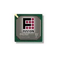
AFS250-FGG256 Actel, AFS250-FGG256 Datasheet - Page 104

AFS250-FGG256
Manufacturer Part Number
AFS250-FGG256
Description
FPGA - Field Programmable Gate Array 250K System Gates
Manufacturer
Actel
Datasheet
1.AFS600-PQG208.pdf
(330 pages)
Specifications of AFS250-FGG256
Processor Series
AFS250
Core
IP Core
Maximum Operating Frequency
1098.9 MHz
Number Of Programmable I/os
114
Data Ram Size
36864
Supply Voltage (max)
1.575 V
Maximum Operating Temperature
+ 70 C
Minimum Operating Temperature
0 C
Development Tools By Supplier
AFS-Eval-Kit, AFS-BRD600, FlashPro 3, FlashPro Lite, Silicon-Explorer II, Silicon-Sculptor 3, SI-EX-TCA
Mounting Style
SMD/SMT
Supply Voltage (min)
1.425 V
Number Of Gates
250 K
Package / Case
FPBGA-256
Lead Free Status / RoHS Status
Lead free / RoHS Compliant
Available stocks
Company
Part Number
Manufacturer
Quantity
Price
Company:
Part Number:
AFS250-FGG256
Manufacturer:
Actel
Quantity:
135
Company:
Part Number:
AFS250-FGG256
Manufacturer:
ACTEL
Quantity:
6 800
Company:
Part Number:
AFS250-FGG256I
Manufacturer:
Microsemi SoC
Quantity:
10 000
- Current page: 104 of 330
- Download datasheet (13Mb)
Device Architecture
2- 88
Terminology
BW is a range of frequencies that a Channel can handle.
A channel is define as an analog input configured as one of the Prescaler range shown in
page
Channel Gain is a measured of the deviation of the actual slope from the ideal slope. The slope is
measured from the 20% and 80% point.
Channel Gain Error is a deviation from the ideal slope of the transfer function. The Prescaler Gain Error
is expressed as the percent difference between the actual and ideal, as shown in
Channel Offset error is measured as the input voltage that causes the transition from zero to a count of
one. An Ideal Prescaler will have offset equal to ½ of LSB voltage. Offset error is a positive or negative
when the first transition point is higher or lower than ideal. Offset error is expressed in LSB or input
voltage.
Total Channel Error is defined as the total error measured compared to the ideal value. Total Channel
Error is the sum of gain error and offset error combined.
measured.
Total Channel Error is defined as the difference between the actual ADC output and ideal ADC output. In
the example shown in
Figure 2-69 • Total Channel Error Example
BW – Bandwidth
Channel
Channel Gain
Channel Gain Error
Channel Input Offset Error
Total Channel Error
2-132. The channel includes the Prescaler circuit and the ADC.
Figure
2-69, the Total Channel Error would be a negative number.
Channel Input
Offset Error
Error
Input Voltage to Prescaler
Gain
Gain
R e visio n 1
=
=
(1-Gain) 100%
Gain
------------------------ -
Gain
T otal C hannel Er r or
actual
ideal
Figure 2-69
×
C hannel G ain
Actual Output
shows how Total Channel Error is
EQ
2.
Table 2-54 on
EQ 1
EQ 2
Related parts for AFS250-FGG256
Image
Part Number
Description
Manufacturer
Datasheet
Request
R

Part Number:
Description:
FPGA 256/I°/Fusion Voltage: 1.5, 1.8, 2.5, 3.3 Mixed Voltage
Manufacturer:
Actel
Datasheet:

Part Number:
Description:
FPGA - Field Programmable Gate Array 250K System Gates
Manufacturer:
Actel
Datasheet:

Part Number:
Description:
MCU, MPU & DSP Development Tools Silicon Sculptor Programming Mod
Manufacturer:
Actel

Part Number:
Description:
MCU, MPU & DSP Development Tools InSystem Programming ProASICPLUS Devices
Manufacturer:
Actel

Part Number:
Description:
Programming Socket Adapters & Emulators PQ160 Module
Manufacturer:
Actel

Part Number:
Description:
Programming Socket Adapters & Emulators Axcelerator Adap Module Kit
Manufacturer:
Actel

Part Number:
Description:
Programming Socket Adapters & Emulators Evaluation
Manufacturer:
Actel

Part Number:
Description:
Programming Socket Adapters & Emulators AFDX Solutions
Manufacturer:
Actel

Part Number:
Description:
Programming Socket Adapters & Emulators SILICON SCULPTOR ADAPTER MODULE
Manufacturer:
Actel
Datasheet:

Part Number:
Description:
Programming Socket Adapters & Emulators Axcelerator Adap Module Kit
Manufacturer:
Actel

Part Number:
Description:
Programming Socket Adapters & Emulators Evaluation
Manufacturer:
Actel

Part Number:
Description:
Programming Socket Adapters & Emulators Silicon Sculptor Software
Manufacturer:
Actel

Part Number:
Description:
Programming Socket Adapters & Emulators InSystem Programming ProASICPLUS Devices
Manufacturer:
Actel


