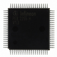
PEB2255H-V13 Infineon Technologies, PEB2255H-V13 Datasheet - Page 296

PEB2255H-V13
Manufacturer Part Number
PEB2255H-V13
Description
IC INTERFACE LINE 80-MQFP
Manufacturer
Infineon Technologies
Datasheet
1.PEB2255H-V13.pdf
(374 pages)
Specifications of PEB2255H-V13
Applications
*
Interface
*
Voltage - Supply
*
Package / Case
80-SQFP
Mounting Type
Surface Mount
Lead Free Status / RoHS Status
Lead free / RoHS Compliant
Other names
PEB2255H-V13
PEB2255H-V13IN
PEB2255H-V13IN
Available stocks
Company
Part Number
Manufacturer
Quantity
Price
Company:
Part Number:
PEB2255H-V13
Manufacturer:
Infineon Technologies
Quantity:
10 000
- Current page: 296 of 374
- Download datasheet (6Mb)
DJA2…
DJA1…
SCF…
ELT…
LOS2...1…
Data Sheet
Digital Jitter Attenuation DCO-X
0…
1…
Digital Jitter Attenuation DCO-R
0…
1…
Select Corner Frequency of DCO-R
Setting this bit reduces the corner frequency of the DCO-R circuit by
the factor of ten to 0.6 Hz.
Reducing the corner frequency of the DCO-R circuitry increases the
synchronization time before the frequencies are synchronized.
Enable Loop-Timed
0…
1…
which is synchronized with the extracted receive route clock. In this
configuration the transmit elastic buffer has to be enabled. Refer to
register FMR5.XTM. For correct operation of loop timed the remote
loop (bit LIM1.RL = 0) must be inactive.
Loss of Signal Recovery condition
00… The LOS alarm is cleared if the predefined pulse density
01… Additionally to the recovery condition described above a LOS
10… Clearing of a LOS alarm is done if the pulse density is fulfilled
11… not assigned
Jitter attenuation of the transmit clock is done using an external
pullable crystal between pins XTAL3/4
Jitter attenuation of the transmit clock is done without using an
external pullable crystal between pins XTAL3/4. Only a free
running 12.352-MHz clock has top be provided at XTAL3 (+/-
50 ppm).
Jitter attenuation of the system/transmit clock is done using an
external pullable crystal between pins XTAL1/2
Jitter attenuation of the system/transmit clock is done without
using an external pullable crystal between pins XTAL1/2. Only
a free running 16.384-MHz clock has top be provided at XTAL1.
normal operation
Transmit clock is generated from the clock supplied by XTAL3
(register PCR) is detected during the time interval which is
defined by register PCD.
alarm is only cleared if the pulse density is fulfilled and no more
than 15 contiguous zeros are detected during the recovery
interval. (according to TR-NWT 499).
and no more than 99 contiguous zeroes are detected during the
recovery interval (according to TR-NWT 820).
296
FALC-LH V1.3
T1/J1 Registers
PEB 2255
2000-07
Related parts for PEB2255H-V13
Image
Part Number
Description
Manufacturer
Datasheet
Request
R

Part Number:
Description:
E1/t1/j1 Framer And Line Interface Component For Long And Short Haul Applications
Manufacturer:
Infineon Technologies Corporation
Datasheet:

Part Number:
Description:
Manufacturer:
Infineon Technologies AG
Datasheet:

Part Number:
Description:
Manufacturer:
Infineon Technologies AG
Datasheet:

Part Number:
Description:
Manufacturer:
Infineon Technologies AG
Datasheet:

Part Number:
Description:
Manufacturer:
Infineon Technologies AG
Datasheet:

Part Number:
Description:
Manufacturer:
Infineon Technologies AG
Datasheet:

Part Number:
Description:
Manufacturer:
Infineon Technologies AG
Datasheet:

Part Number:
Description:
Manufacturer:
Infineon Technologies AG
Datasheet:

Part Number:
Description:
16-bit microcontroller with 2x2 KByte RAM
Manufacturer:
Infineon Technologies AG
Datasheet:

Part Number:
Description:
NPN silicon RF transistor
Manufacturer:
Infineon Technologies AG
Datasheet:

Part Number:
Description:
NPN silicon RF transistor
Manufacturer:
Infineon Technologies AG
Datasheet:

Part Number:
Description:
NPN silicon RF transistor
Manufacturer:
Infineon Technologies AG
Datasheet:

Part Number:
Description:
NPN silicon RF transistor
Manufacturer:
Infineon Technologies AG
Datasheet:

Part Number:
Description:
Si-MMIC-amplifier in SIEGET 25-technologie
Manufacturer:
Infineon Technologies AG
Datasheet:

Part Number:
Description:
IGBT Power Module
Manufacturer:
Infineon Technologies AG
Datasheet:


