AN2131-DK001 Cypress Semiconductor Corp, AN2131-DK001 Datasheet - Page 209
AN2131-DK001
Manufacturer Part Number
AN2131-DK001
Description
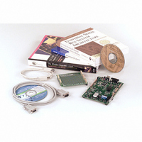
KIT EZ-USB DEVELOPMENT BOARD
Manufacturer
Cypress Semiconductor Corp
Datasheet
1.AN2131SC.pdf
(334 pages)
Specifications of AN2131-DK001
Lead Free Status / RoHS Status
Contains lead / RoHS non-compliant
Other names
428-1333


The 8051 uses these registers to transfer data over the EZ-USB I
Bit 7:
The 8051 sets the START bit to “1” to prepare an I
8051 load to I2DAT will generate the start condition followed by the serialized byte of
data in I2DAT. The 8051 loads byte data into I2DAT after setting the START bit. The I
controller clears the START bit during the ACK interval.
Bit 6:
The 8051 sets STOP=1 to terminate an I
STOP bit after completing the STOP condition. If the 8051 sets the STOP bit during a
byte transfer, the STOP condition will be generated immediately following the ACK phase
of the byte transfer. If no byte transfer is occurring when the STOP bit is set, the STOP
condition will be carried out immediately on the bus. Data should not be written to I2CS
or I2DAT until the STOP bit returns low.
Page 12-16
I2CS
I2DAT
12.10 I
START
R/W
R/W
D7
b7
b7
0
x
2
C Registers
STOP
START
STOP
R/W
R/W
D6
b6
b6
0
x
LASTRD
R/W
R/W
D5
b5
b5
0
x
Figure 12-14. I
Signal START condition
Signal STOP condition
I
Chapter 12. EZ-USB Registers
2
C Control and Status
R/W
ID1
D4
b4
b4
R
x
x
I
2
C bus transfer. The I
2
C Data
2
C Transfer Registers
ID0
R/W
D3
b3
b3
R
x
x
2
C bus transfer. If START=1, the next
BERR
R/W
D2
b2
b2
R
0
x
2
C controller clears the
2
C bus.
ACK
R/W
D1
b1
b1
R
0
x
EZ-USB TRM v1.9
DONE
R/W
D0
b0
b0
R
0
x
7FA5
7FA6
2
C
Related parts for AN2131-DK001
Image
Part Number
Description
Manufacturer
Datasheet
Request
R

Part Number:
Description:
Two Chip Voltage Controlled Amplifier & Video Switch
Manufacturer:
Analog Devices

Part Number:
Description:
Manufacturer:
Cypress Semiconductor Corp
Datasheet:
Part Number:
Description:
Manufacturer:
Cypress Semiconductor Corp
Datasheet:
Part Number:
Description:
Manufacturer:
Cypress Semiconductor Corp
Datasheet:
Part Number:
Description:
Manufacturer:
Cypress Semiconductor Corp
Datasheet:
Part Number:
Description:
Manufacturer:
Cypress Semiconductor Corp
Datasheet: