AN2131-DK001 Cypress Semiconductor Corp, AN2131-DK001 Datasheet - Page 99
AN2131-DK001
Manufacturer Part Number
AN2131-DK001
Description
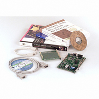
KIT EZ-USB DEVELOPMENT BOARD
Manufacturer
Cypress Semiconductor Corp
Datasheet
1.AN2131SC.pdf
(334 pages)
Specifications of AN2131-DK001
Lead Free Status / RoHS Status
Contains lead / RoHS non-compliant
Other names
428-1333


The USB specification allows maximum packet sizes of 8, 16, 32, or 64 bytes for bulk
data, and 1 - 64 bytes for interrupt data. EZ-USB provides the maximum 64 bytes of
buffer space for each of its sixteen endpoints 0-7 IN and 0-7 OUT. Six of the bulk end-
points, 2-IN, 4-IN, 6-IN, 2-OUT, 4-OUT, and 6-OUT may be paired with the next consec-
utively numbered endpoint to provide double-buffering, which allows one data packet to
be serviced by the 8051 while another is in transit over USB. Six endpoint pairing bits
(USBPAIR register) control double-buffering.
The 8051 sets fourteen endpoint valid bits (IN07VAL, OUT07VAL registers) at initializa-
tion time to tell the EZ-USB core which endpoints are active. The default CONTROL
endpoint zero is always valid.
Bulk data appears in RAM. Each bulk endpoint has a reserved 64-byte RAM space, a 7-
bit count register, and a 2-bit control and status (CS) register. The 8051 can read one bit of
the CS register to determine endpoint busy, and write the other to force an endpoint
STALL condition.
The 8051 should never read or write an endpoint buffer or byte count register while the
endpoint’s busy bit is set.
When an endpoint becomes ready for 8051 service, the EZ-USB core sets an interrupt
request bit. The EZ-USB vectored interrupt system separates the interrupt requests by
endpoint to automatically transfer control to the ISR (Interrupt Service Routine) for the
endpoint requiring service. Chapter 9, "EZ-USB Interrupts" fully describes this mecha-
nism.
Figure 6-2 illustrates the registers and bits associated with bulk transfers.
Page 6-2
Chapter 6. EZ-USB CPU
EZ-USB TRM v1.9
Related parts for AN2131-DK001
Image
Part Number
Description
Manufacturer
Datasheet
Request
R

Part Number:
Description:
Two Chip Voltage Controlled Amplifier & Video Switch
Manufacturer:
Analog Devices

Part Number:
Description:
Manufacturer:
Cypress Semiconductor Corp
Datasheet:
Part Number:
Description:
Manufacturer:
Cypress Semiconductor Corp
Datasheet:
Part Number:
Description:
Manufacturer:
Cypress Semiconductor Corp
Datasheet:
Part Number:
Description:
Manufacturer:
Cypress Semiconductor Corp
Datasheet:
Part Number:
Description:
Manufacturer:
Cypress Semiconductor Corp
Datasheet: