AN2131-DK001 Cypress Semiconductor Corp, AN2131-DK001 Datasheet - Page 219
AN2131-DK001
Manufacturer Part Number
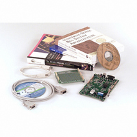
AN2131-DK001
Description
KIT EZ-USB DEVELOPMENT BOARD
Manufacturer
Cypress Semiconductor Corp
Datasheet
1.AN2131SC.pdf
(334 pages)
Specifications of AN2131-DK001
Lead Free Status / RoHS Status
Contains lead / RoHS non-compliant
Other names
428-1333


Bit 3:
The BREAK bit is set when the 8051 address bus matches the address held in the bit
breakpoint address registers (next page). The BKPT pin reflects the state of this bit. The
8051 writes a “1” to the BREAK bit to clear it. It is not necessary to clear the BREAK bit
if the pulse mode bit (BPPULSE) is set.
Bit 2:
The 8051 sets this bit to “1” to pulse the BREAK bit (and BKPT pin) high for 8 CLK24
cycles when the 8051 address bus matches the address held in the breakpoint address reg-
isters. when this bit is set to “0,” the BREAK bit (and BKPT pin) remains high until it is
cleared by the 8051.
Bit 1:
If this bit is “1,” a BREAK signal is generated whenever the 16-bit address lines match the
value in the Breakpoint Address Registers (BPADDRH/L). The behavior of the BREAK
bit and associated BKPT pin signal is either latched or pulsed, depending on the state of
the BPPULSE bit.
Bit 0:
If this bit is “1,” the EZ-USB Auto-vector feature is enabled. If it is 0, the auto-vector fea-
ture is disabled. See Chapter 9, "EZ-USB Interrupts" for more information on the auto-
vector feature.
Page 12-26
USBBAV
R/W
b7
0
-
BREAK
BPPULSE
BPEN
AVEN
R/W
b6
0
-
Figure 12-21. Breakpoint and Autovector Register
R/W
b5
0
-
Breakpoint enable
Breakpoint pulse mode
Breakpoint enable
Auto-vector enable
Breakpoint and Autovector
Chapter 12. EZ-USB Registers
R/W
b4
0
-
BREAK
R/W
b3
0
BPPULSE
R/W
b2
0
BPEN
R/W
b1
0
EZ-USB TRM v1.9
AVEN
R/W
b0
7FAF
0
Related parts for AN2131-DK001
Image
Part Number
Description
Manufacturer
Datasheet
Request
R

Part Number:
Description:
Two Chip Voltage Controlled Amplifier & Video Switch
Manufacturer:
Analog Devices

Part Number:
Description:
Manufacturer:
Cypress Semiconductor Corp
Datasheet:
Part Number:
Description:
Manufacturer:
Cypress Semiconductor Corp
Datasheet:
Part Number:
Description:
Manufacturer:
Cypress Semiconductor Corp
Datasheet:
Part Number:
Description:
Manufacturer:
Cypress Semiconductor Corp
Datasheet:
Part Number:
Description:
Manufacturer:
Cypress Semiconductor Corp
Datasheet: