MC9S08JM16CGT Freescale Semiconductor, MC9S08JM16CGT Datasheet - Page 157
MC9S08JM16CGT
Manufacturer Part Number
MC9S08JM16CGT
Description
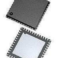
MCU 8BIT 16K FLASH 48-QFN
Manufacturer
Freescale Semiconductor
Series
HCS08r
Datasheet
1.DEMO9S08JM16.pdf
(386 pages)
Specifications of MC9S08JM16CGT
Core Processor
HCS08
Core Size
8-Bit
Speed
48MHz
Connectivity
I²C, LIN, SCI, SPI, USB
Peripherals
LVD, POR, PWM, WDT
Number Of I /o
37
Program Memory Size
16KB (16K x 8)
Program Memory Type
FLASH
Ram Size
1K x 8
Voltage - Supply (vcc/vdd)
2.7 V ~ 5.5 V
Data Converters
A/D 8x12b
Oscillator Type
External
Operating Temperature
-40°C ~ 85°C
Package / Case
48-QFN Exposed Pad
Processor Series
S08JM
Core
HCS08
Data Bus Width
8 bit
Data Ram Size
1 KB
Interface Type
I2C, SPI
Maximum Clock Frequency
48 MHz
Number Of Programmable I/os
37
Number Of Timers
2
Operating Supply Voltage
2.7 V to 5.5 V
Maximum Operating Temperature
+ 85 C
Mounting Style
SMD/SMT
3rd Party Development Tools
EWS08
Development Tools By Supplier
DEMOJM, DEMOJMSKT, DEMOFLEXISJMSD, DEMO9S08JM16
Minimum Operating Temperature
- 40 C
On-chip Adc
12 bit, 8 Channel
Controller Family/series
HCS08
No. Of I/o's
37
Ram Memory Size
1KB
Cpu Speed
48MHz
No. Of Timers
2
Digital Ic Case Style
QFN
Rohs Compliant
Yes
Lead Free Status / RoHS Status
Lead free / RoHS Compliant
Eeprom Size
-
Lead Free Status / Rohs Status
Lead free / RoHS Compliant
Available stocks
Company
Part Number
Manufacturer
Quantity
Price
Company:

Part Number:
MC9S08JM16CGT
Manufacturer:
PIXART
Quantity:
1 001
Part Number:
MC9S08JM16CGT
Manufacturer:
FREESCALE
Quantity:
20 000


There are some situations where external system activity causes radiated or conducted noise emissions or
excessive V
wait or stop3 or I/O activity cannot be halted, these recommended actions may reduce the effect of noise
on the accuracy:
10.6.2.4
The ADC quantizes the ideal straight-line transfer function into 4096 steps (in 12-bit mode). Each step
ideally has the same height (1 code) and width. The width is defined as the delta between the transition
points to one code and the next. The ideal code width for an N bit converter (in this case N can be 8, 10 or
12), defined as 1
There is an inherent quantization error due to the digitization of the result. For 8-bit or 10-bit conversions
the code transitions when the voltage is at the midpoint between the points where the straight line transfer
function is exactly represented by the actual transfer function. Therefore, the quantization error will be
±1/2 lsb in 8- or 10-bit mode. As a consequence, however, the code width of the first (0x000) conversion
is only 1/2 lsb and the code width of the last (0xFF or 0x3FF) is 1.5 lsb.
For 12-bit conversions the code transitions only after the full code width is present, so the quantization
error is −1 lsb to 0 lsb and the code width of each step is 1 lsb.
10.6.2.5
The ADC may also exhibit non-linearity of several forms. Every effort has been made to reduce these
errors but the system must be aware of them because they affect overall accuracy. These errors are:
Freescale Semiconductor
•
•
•
•
•
•
•
There is no I/O switching, input or output, on the MCU during the conversion.
Place a 0.01 μF capacitor (C
noise issues, but affects the sample rate based on the external analog source resistance).
Average the result by converting the analog input many times in succession and dividing the sum
of the results. Four samples are required to eliminate the effect of a 1
Reduce the effect of synchronous noise by operating off the asynchronous clock (ADACK) and
averaging. Noise that is synchronous to ADCK cannot be averaged out.
Zero-scale error (E
the actual code width of the first conversion and the ideal code width (1/2 lsb in 8-bit or 10-bit
modes and 1 lsb in 12-bit mode). If the first conversion is 0x001, the difference between the actual
0x001 code width and its ideal (1 lsb) is used.
Full-scale error (E
the last conversion and the ideal code width (1.5 lsb in 8-bit or 10-bit modes and 1
mode). If the last conversion is 0x3FE, the difference between the actual 0x3FE code width and its
ideal (1
Differential non-linearity (DNL) — This error is defined as the worst-case difference between the
actual code width and the ideal code width for all conversions.
DD
Code Width and Quantization Error
Linearity Errors
LSB
noise is coupled into the ADC. In these situations, or when the MCU cannot be placed in
LSB
) is used.
, is:
FS
ZS
) — This error is defined as the difference between the actual code width of
) (sometimes called offset) — This error is defined as the difference between
1 lsb = (V
MC9S08JM16 Series Data Sheet, Rev. 2
AS
) on the selected input channel to V
REFH
– V
REFL
) / 2
N
Analog-to-Digital Converter (S08ADC12V1)
REFL
LSB
or V
, one-time error.
SSAD
(this improves
LSB
in 12-bit
Eqn. 10-2
157
Related parts for MC9S08JM16CGT
Image
Part Number
Description
Manufacturer
Datasheet
Request
R

Part Number:
Description:
Manufacturer:
Freescale Semiconductor, Inc
Datasheet:
Part Number:
Description:
Manufacturer:
Freescale Semiconductor, Inc
Datasheet:
Part Number:
Description:
Manufacturer:
Freescale Semiconductor, Inc
Datasheet:
Part Number:
Description:
Manufacturer:
Freescale Semiconductor, Inc
Datasheet:
Part Number:
Description:
Manufacturer:
Freescale Semiconductor, Inc
Datasheet:
Part Number:
Description:
Manufacturer:
Freescale Semiconductor, Inc
Datasheet:
Part Number:
Description:
Manufacturer:
Freescale Semiconductor, Inc
Datasheet:
Part Number:
Description:
Manufacturer:
Freescale Semiconductor, Inc
Datasheet:
Part Number:
Description:
Manufacturer:
Freescale Semiconductor, Inc
Datasheet:
Part Number:
Description:
Manufacturer:
Freescale Semiconductor, Inc
Datasheet:
Part Number:
Description:
Manufacturer:
Freescale Semiconductor, Inc
Datasheet:
Part Number:
Description:
Manufacturer:
Freescale Semiconductor, Inc
Datasheet:
Part Number:
Description:
Manufacturer:
Freescale Semiconductor, Inc
Datasheet:
Part Number:
Description:
Manufacturer:
Freescale Semiconductor, Inc
Datasheet:
Part Number:
Description:
Manufacturer:
Freescale Semiconductor, Inc
Datasheet: