MC9S08JM16CGT Freescale Semiconductor, MC9S08JM16CGT Datasheet - Page 16
MC9S08JM16CGT
Manufacturer Part Number
MC9S08JM16CGT
Description
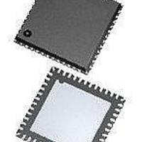
MCU 8BIT 16K FLASH 48-QFN
Manufacturer
Freescale Semiconductor
Series
HCS08r
Datasheet
1.DEMO9S08JM16.pdf
(386 pages)
Specifications of MC9S08JM16CGT
Core Processor
HCS08
Core Size
8-Bit
Speed
48MHz
Connectivity
I²C, LIN, SCI, SPI, USB
Peripherals
LVD, POR, PWM, WDT
Number Of I /o
37
Program Memory Size
16KB (16K x 8)
Program Memory Type
FLASH
Ram Size
1K x 8
Voltage - Supply (vcc/vdd)
2.7 V ~ 5.5 V
Data Converters
A/D 8x12b
Oscillator Type
External
Operating Temperature
-40°C ~ 85°C
Package / Case
48-QFN Exposed Pad
Processor Series
S08JM
Core
HCS08
Data Bus Width
8 bit
Data Ram Size
1 KB
Interface Type
I2C, SPI
Maximum Clock Frequency
48 MHz
Number Of Programmable I/os
37
Number Of Timers
2
Operating Supply Voltage
2.7 V to 5.5 V
Maximum Operating Temperature
+ 85 C
Mounting Style
SMD/SMT
3rd Party Development Tools
EWS08
Development Tools By Supplier
DEMOJM, DEMOJMSKT, DEMOFLEXISJMSD, DEMO9S08JM16
Minimum Operating Temperature
- 40 C
On-chip Adc
12 bit, 8 Channel
Controller Family/series
HCS08
No. Of I/o's
37
Ram Memory Size
1KB
Cpu Speed
48MHz
No. Of Timers
2
Digital Ic Case Style
QFN
Rohs Compliant
Yes
Lead Free Status / RoHS Status
Lead free / RoHS Compliant
Eeprom Size
-
Lead Free Status / Rohs Status
Lead free / RoHS Compliant
Available stocks
Company
Part Number
Manufacturer
Quantity
Price
Company:

Part Number:
MC9S08JM16CGT
Manufacturer:
PIXART
Quantity:
1 001
Part Number:
MC9S08JM16CGT
Manufacturer:
FREESCALE
Quantity:
20 000


15.5 Initialization/Application Information ..........................................................................................263
16.1 Introduction ...................................................................................................................................267
16.2 Signal Description .........................................................................................................................272
16.3 Register Definition ........................................................................................................................276
16.4 Functional Description ..................................................................................................................282
16.5 Reset Overview .............................................................................................................................288
16.6 Interrupts .......................................................................................................................................288
17.1 Introduction ...................................................................................................................................295
16
15.4.2 Master Mode ...................................................................................................................252
15.4.3 Slave Mode .....................................................................................................................253
15.4.4 Data Transmission Length ..............................................................................................254
15.4.5 SPI Clock Formats ..........................................................................................................255
15.4.6 SPI Baud Rate Generation ..............................................................................................257
15.4.7 Special Features ..............................................................................................................258
15.4.8 Error Conditions .............................................................................................................259
15.4.9 Low Power Mode Options ..............................................................................................260
15.4.10SPI Interrupts ..................................................................................................................261
15.5.1 SPI Module Initialization Example .................................................................................263
16.1.1 Features ...........................................................................................................................269
16.1.2 Modes of Operation ........................................................................................................269
16.1.3 Block Diagram ................................................................................................................270
16.2.1 Detailed Signal Descriptions ..........................................................................................272
16.3.1 TPM Status and Control Register (TPMxSC) ................................................................276
16.3.2 TPM-Counter Registers (TPMxCNTH:TPMxCNTL) ....................................................277
16.3.3 TPM Counter Modulo Registers (TPMxMODH:TPMxMODL) ....................................278
16.3.4 TPM Channel n Status and Control Register (TPMxCnSC) ..........................................279
16.3.5 TPM Channel Value Registers (TPMxCnVH:TPMxCnVL) ..........................................281
16.4.1 Counter ............................................................................................................................283
16.4.2 Channel Mode Selection .................................................................................................285
16.5.1 General ............................................................................................................................288
16.5.2 Description of Reset Operation .......................................................................................288
16.6.1 General ............................................................................................................................288
16.6.2 Description of Interrupt Operation .................................................................................289
17.1.1 Clocking Requirements ...................................................................................................295
17.1.2 Current Consumption in USB Suspend ..........................................................................295
17.1.3 3.3 V Regulator ...............................................................................................................295
17.1.4 Features ...........................................................................................................................298
17.1.5 Modes of Operation ........................................................................................................298
17.1.6 Block Diagram ................................................................................................................299
Universal Serial Bus Device Controller (S08USBV1)
Timer/Pulse-Width Modulator (S08TPMV2)
MC9S08JM16 Series Data Sheet, Rev. 2
Chapter 16
Chapter 17
Freescale Semiconductor
Related parts for MC9S08JM16CGT
Image
Part Number
Description
Manufacturer
Datasheet
Request
R

Part Number:
Description:
Manufacturer:
Freescale Semiconductor, Inc
Datasheet:
Part Number:
Description:
Manufacturer:
Freescale Semiconductor, Inc
Datasheet:
Part Number:
Description:
Manufacturer:
Freescale Semiconductor, Inc
Datasheet:
Part Number:
Description:
Manufacturer:
Freescale Semiconductor, Inc
Datasheet:
Part Number:
Description:
Manufacturer:
Freescale Semiconductor, Inc
Datasheet:
Part Number:
Description:
Manufacturer:
Freescale Semiconductor, Inc
Datasheet:
Part Number:
Description:
Manufacturer:
Freescale Semiconductor, Inc
Datasheet:
Part Number:
Description:
Manufacturer:
Freescale Semiconductor, Inc
Datasheet:
Part Number:
Description:
Manufacturer:
Freescale Semiconductor, Inc
Datasheet:
Part Number:
Description:
Manufacturer:
Freescale Semiconductor, Inc
Datasheet:
Part Number:
Description:
Manufacturer:
Freescale Semiconductor, Inc
Datasheet:
Part Number:
Description:
Manufacturer:
Freescale Semiconductor, Inc
Datasheet:
Part Number:
Description:
Manufacturer:
Freescale Semiconductor, Inc
Datasheet:
Part Number:
Description:
Manufacturer:
Freescale Semiconductor, Inc
Datasheet:
Part Number:
Description:
Manufacturer:
Freescale Semiconductor, Inc
Datasheet: