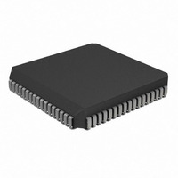
PIC17LC752T-08I/L Microchip Technology, PIC17LC752T-08I/L Datasheet - Page 207

PIC17LC752T-08I/L
Manufacturer Part Number
PIC17LC752T-08I/L
Description
IC MCU OTP 8KX16 A/D 68PLCC
Manufacturer
Microchip Technology
Series
PIC® 17Cr
Specifications of PIC17LC752T-08I/L
Core Processor
PIC
Core Size
8-Bit
Speed
8MHz
Connectivity
I²C, SPI, UART/USART
Peripherals
Brown-out Detect/Reset, POR, PWM, WDT
Number Of I /o
50
Program Memory Size
16KB (8K x 16)
Program Memory Type
OTP
Ram Size
678 x 8
Voltage - Supply (vcc/vdd)
3 V ~ 5.5 V
Data Converters
A/D 12x10b
Oscillator Type
External
Operating Temperature
-40°C ~ 85°C
Package / Case
68-PLCC
Processor Series
PIC17LC
Core
PIC
Data Bus Width
8 bit
Data Ram Size
678 B
Interface Type
I2C, MSSP, RS- 232, SCI, SPI, USART
Maximum Clock Frequency
8 MHz
Number Of Programmable I/os
50
Number Of Timers
8
Operating Supply Voltage
3 V to 5.5 V
Maximum Operating Temperature
+ 85 C
Mounting Style
SMD/SMT
Development Tools By Supplier
ICE2000, DM173001
Minimum Operating Temperature
- 40 C
On-chip Adc
12 bit
Lead Free Status / RoHS Status
Lead free / RoHS Compliant
Eeprom Size
-
Lead Free Status / Rohs Status
Details
Available stocks
Company
Part Number
Manufacturer
Quantity
Price
Company:
Part Number:
PIC17LC752T-08I/L
Manufacturer:
Microchip Technology
Quantity:
10 000
- Current page: 207 of 304
- Download datasheet (6Mb)
CALL
Syntax:
Operands:
Operation:
Status Affected:
Encoding:
Description:
Words:
Cycles:
Q Cycle Activity:
Example:
2000 Microchip Technology Inc.
Before Instruction
After Instruction
operation
Decode
PC =
PC =
TOS =
Q1
No
Address (HERE)
Address (THERE)
Address (HERE + 1)
Read literal
Push PC to
operation
Subroutine Call
[ label ] CALL k
0
PC+ 1
k<12:8>
PC<15:13>
None
Subroutine call within 8K page. First,
return address (PC+1) is pushed onto
the stack. The 13-bit value is loaded
into PC bits<12:0>. Then the upper-
eight bits of the PC are copied into
PCLATH. CALL is a two-cycle
instruction.
See LCALL for calls outside 8K memory
space.
1
2
HERE
’k’<7:0>,
stack
111k
Q2
No
k
8191
TOS, k
kkkk
CALL
PCLATH<4:0>;
operation
Process
Data
PCLATH<7:5>
Q3
No
THERE
PC<12:0>,
kkkk
Write to PC
operation
Q4
No
kkkk
CLRF
Syntax:
Operands:
Operation:
Status Affected:
Encoding:
Description:
Words:
Cycles:
Q Cycle Activity:
Example:
Before Instruction
After Instruction
Decode
FLAG_REG
WREG
FLAG_REG
WREG
Q1
register ’f’
Clear f
[label] CLRF
0
00h
00h
None
Clears the contents of the specified
register(s).
s = 0: Data memory location ’f’ and
WREG are cleared.
s = 1: Data memory location ’f’ is
cleared.
1
1
CLRF
Read
0010
Q2
=
=
=
=
f
PIC17C7XX
255
f, s
dest
0x5A
0x01
0x00
0x01
FLAG_REG, 1
100s
Process
[0,1]
Data
f,s
Q3
DS30289B-page 207
ffff
register ’f’
specified
WREG
and if
Write
Q4
ffff
Related parts for PIC17LC752T-08I/L
Image
Part Number
Description
Manufacturer
Datasheet
Request
R

Part Number:
Description:
IC MCU OTP 8KX16 A/D 68PLCC
Manufacturer:
Microchip Technology
Datasheet:

Part Number:
Description:
IC MCU OTP 8KX16 A/D 68PLCC
Manufacturer:
Microchip Technology
Datasheet:

Part Number:
Description:
IC MCU OTP 8KX16 A/D 64TQFP
Manufacturer:
Microchip Technology
Datasheet:

Part Number:
Description:
IC MCU OTP 8KX16 A/D 64TQFP
Manufacturer:
Microchip Technology
Datasheet:

Part Number:
Description:
Manufacturer:
Microchip Technology Inc.
Datasheet:

Part Number:
Description:
Manufacturer:
Microchip Technology Inc.
Datasheet:

Part Number:
Description:
Manufacturer:
Microchip Technology Inc.
Datasheet:

Part Number:
Description:
Manufacturer:
Microchip Technology Inc.
Datasheet:

Part Number:
Description:
Manufacturer:
Microchip Technology Inc.
Datasheet:

Part Number:
Description:
Manufacturer:
Microchip Technology Inc.
Datasheet:

Part Number:
Description:
Manufacturer:
Microchip Technology Inc.
Datasheet:


