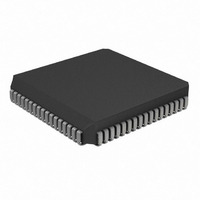
PIC17LC752T-08I/L Microchip Technology, PIC17LC752T-08I/L Datasheet - Page 52

PIC17LC752T-08I/L
Manufacturer Part Number
PIC17LC752T-08I/L
Description
IC MCU OTP 8KX16 A/D 68PLCC
Manufacturer
Microchip Technology
Series
PIC® 17Cr
Specifications of PIC17LC752T-08I/L
Core Processor
PIC
Core Size
8-Bit
Speed
8MHz
Connectivity
I²C, SPI, UART/USART
Peripherals
Brown-out Detect/Reset, POR, PWM, WDT
Number Of I /o
50
Program Memory Size
16KB (8K x 16)
Program Memory Type
OTP
Ram Size
678 x 8
Voltage - Supply (vcc/vdd)
3 V ~ 5.5 V
Data Converters
A/D 12x10b
Oscillator Type
External
Operating Temperature
-40°C ~ 85°C
Package / Case
68-PLCC
Processor Series
PIC17LC
Core
PIC
Data Bus Width
8 bit
Data Ram Size
678 B
Interface Type
I2C, MSSP, RS- 232, SCI, SPI, USART
Maximum Clock Frequency
8 MHz
Number Of Programmable I/os
50
Number Of Timers
8
Operating Supply Voltage
3 V to 5.5 V
Maximum Operating Temperature
+ 85 C
Mounting Style
SMD/SMT
Development Tools By Supplier
ICE2000, DM173001
Minimum Operating Temperature
- 40 C
On-chip Adc
12 bit
Lead Free Status / RoHS Status
Lead free / RoHS Compliant
Eeprom Size
-
Lead Free Status / Rohs Status
Details
Available stocks
Company
Part Number
Manufacturer
Quantity
Price
Company:
Part Number:
PIC17LC752T-08I/L
Manufacturer:
Microchip Technology
Quantity:
10 000
- Current page: 52 of 304
- Download datasheet (6Mb)
PIC17C7XX
7.2.2.2
The CPUSTA register contains the status and control
bits for the CPU. This register has a bit that is used to
globally enable/disable interrupts. If only a specific
interrupt is desired to be enabled/disabled, please refer
to the Interrupt Status (INTSTA) register and the
Peripheral Interrupt Enable (PIE) registers. The
CPUSTA register also indicates if the stack is available
and contains the Power-down (PD) and Time-out (TO)
bits. The TO, PD, and STKAV bits are not writable.
These bits are set and cleared according to device
REGISTER 7-2: CPUSTA REGISTER (ADDRESS: 06h, UNBANKED)
DS30289B-page 52
bit 7-6
bit 5
bit 4
bit 3
bit 2
bit 1
bit 0
CPU Status Register (CPUSTA)
Legend:
R = Readable bit
- n = Value at POR Reset
bit 7
Unimplemented: Read as '0'
STKAV: Stack Available bit
This bit indicates that the 4-bit stack pointer value is Fh, or has rolled over from Fh
(stack overflow).
1 = Stack is available
0 = Stack is full, or a stack overflow may have occurred (once this bit has been cleared by a
GLINTD: Global Interrupt Disable bit
This bit disables all interrupts. When enabling interrupts, only the sources with their enable bits
set can cause an interrupt.
1 = Disable all interrupts
0 = Enables all unmasked interrupts
TO: WDT Time-out Status bit
1 = After power-up, by a CLRWDT instruction, or by a SLEEP instruction
0 = A Watchdog Timer time-out occurred
PD: Power-down Status bit
1 = After power-up or by the CLRWDT instruction
0 = By execution of the SLEEP instruction
POR: Power-on Reset Status bit
1 = No Power-on Reset occurred
0 = A Power-on Reset occurred (must be set by software)
BOR: Brown-out Reset Status bit
When BODEN Configuration bit is set (enabled):
1 = No Brown-out Reset occurred
0 = A Brown-out Reset occurred (must be set by software)
When BODEN Configuration bit is clear (disabled):
Don’t care
U-0
—
stack overflow, only a device RESET will set this bit)
U-0
—
STKAV
R-1
W = Writable bit
’1’ = Bit is set
GLINTD
R/W-1
logic. Therefore, the result of an instruction with the
CPUSTA register as destination may be different than
intended.
The POR bit allows the differentiation between a
Power-on Reset, external MCLR Reset, or a WDT
Reset. The BOR bit indicates if a Brown-out Reset
occurred.
Note 1: The BOR status bit is a don’t care and is
U = Unimplemented bit, read as ‘0’
’0’ = Bit is cleared
R-1
TO
not necessarily predictable if the Brown-out
circuit is disabled (when the BODEN bit in
the Configuration word is programmed).
R-1
PD
2000 Microchip Technology Inc.
x = Bit is unknown
R/W-0
POR
0h
R/W-1
BOR
bit 0
Related parts for PIC17LC752T-08I/L
Image
Part Number
Description
Manufacturer
Datasheet
Request
R

Part Number:
Description:
IC MCU OTP 8KX16 A/D 68PLCC
Manufacturer:
Microchip Technology
Datasheet:

Part Number:
Description:
IC MCU OTP 8KX16 A/D 68PLCC
Manufacturer:
Microchip Technology
Datasheet:

Part Number:
Description:
IC MCU OTP 8KX16 A/D 64TQFP
Manufacturer:
Microchip Technology
Datasheet:

Part Number:
Description:
IC MCU OTP 8KX16 A/D 64TQFP
Manufacturer:
Microchip Technology
Datasheet:

Part Number:
Description:
Manufacturer:
Microchip Technology Inc.
Datasheet:

Part Number:
Description:
Manufacturer:
Microchip Technology Inc.
Datasheet:

Part Number:
Description:
Manufacturer:
Microchip Technology Inc.
Datasheet:

Part Number:
Description:
Manufacturer:
Microchip Technology Inc.
Datasheet:

Part Number:
Description:
Manufacturer:
Microchip Technology Inc.
Datasheet:

Part Number:
Description:
Manufacturer:
Microchip Technology Inc.
Datasheet:

Part Number:
Description:
Manufacturer:
Microchip Technology Inc.
Datasheet:


