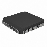
PIC17LC752T-08I/L Microchip Technology, PIC17LC752T-08I/L Datasheet - Page 245

PIC17LC752T-08I/L
Manufacturer Part Number
PIC17LC752T-08I/L
Description
IC MCU OTP 8KX16 A/D 68PLCC
Manufacturer
Microchip Technology
Series
PIC® 17Cr
Specifications of PIC17LC752T-08I/L
Core Processor
PIC
Core Size
8-Bit
Speed
8MHz
Connectivity
I²C, SPI, UART/USART
Peripherals
Brown-out Detect/Reset, POR, PWM, WDT
Number Of I /o
50
Program Memory Size
16KB (8K x 16)
Program Memory Type
OTP
Ram Size
678 x 8
Voltage - Supply (vcc/vdd)
3 V ~ 5.5 V
Data Converters
A/D 12x10b
Oscillator Type
External
Operating Temperature
-40°C ~ 85°C
Package / Case
68-PLCC
Processor Series
PIC17LC
Core
PIC
Data Bus Width
8 bit
Data Ram Size
678 B
Interface Type
I2C, MSSP, RS- 232, SCI, SPI, USART
Maximum Clock Frequency
8 MHz
Number Of Programmable I/os
50
Number Of Timers
8
Operating Supply Voltage
3 V to 5.5 V
Maximum Operating Temperature
+ 85 C
Mounting Style
SMD/SMT
Development Tools By Supplier
ICE2000, DM173001
Minimum Operating Temperature
- 40 C
On-chip Adc
12 bit
Lead Free Status / RoHS Status
Lead free / RoHS Compliant
Eeprom Size
-
Lead Free Status / Rohs Status
Details
Available stocks
Company
Part Number
Manufacturer
Quantity
Price
Company:
Part Number:
PIC17LC752T-08I/L
Manufacturer:
Microchip Technology
Quantity:
10 000
- Current page: 245 of 304
- Download datasheet (6Mb)
DC CHARACTERISTICS
Note 1: In RC oscillator configuration, the OSC1/CLKIN pin is a Schmitt Trigger input. It is not recommended that the
2000 Microchip Technology Inc.
Param.
D063B
D060
D061
D062
D063
D064
D070
D080
D081
D082
D083
D084
D090
D091
D093
D094
†
No.
2: The leakage current on the MCLR pin is strongly dependent on the applied voltage level. Higher leakage
3: Negative current is defined as current sourced by the pin.
4: These specifications are for the programming of the on-chip program memory EPROM through the use of the
5: The MCLR/V
6: For TTL buffers, the better of the two specifications may be used.
Data in “Typ” column is at 5V, 25 C unless otherwise stated.
PIC17CXXX devices be driven with external clock in RC mode.
current may be measured at different input voltages.
table write instructions. The complete programming specifications can be found in: PIC17C7XX Programming
Specifications (Literature number DS TBD).
I
I
V
V
IL
PURB
Sym
OL
OH
Input Leakage Current
(Notes 2, 3)
I/O ports (except RA2, RA3)
MCLR, TEST
RA2, RA3
OSC1 (EC, RC modes)
OSC1 (XT, LF modes)
MCLR, TEST
PORTB Weak Pull-up Current
Output Low Voltage
I/O ports
with TTL buffer
RA2 and RA3
OSC2/CLKOUT
(RC and EC osc modes)
Output High Voltage (Note 3)
I/O ports (except RA2 and
RA3)
with TTL buffer
OSC2/CLKOUT
(RC and EC osc modes)
PP
pin may be kept in this range at times other than programming, but is not recommended.
Characteristic
Standard Operating Conditions (unless otherwise stated)
Operating temperature
Operating voltage V
0.9V
0.9V
0.9V
Min
2.4
2.4
85
–
–
–
–
–
–
–
–
–
–
–
–
DD
DD
DD
Typ†
130
–
–
–
–
–
–
–
–
–
–
–
–
–
–
–
–
–
DD
range as described in Section 20.1
0.1V
0.1V
0.1V
-40°C
-40°C
0°C
V
Max
260
0.4
3.0
0.6
0.4
25
PIN
–
–
–
–
–
1
2
2
1
DD
DD
DD
Units
PIC17C7XX
T
T
T
V
V
V
V
V
V
V
V
V
V
V
V
A
A
A
A
A
A
A
A
A
A
+85°C for industrial
+70°C for commercial
+125°C for extended
Vss
I/O Pin (in digital mode) at
hi-impedance PORTB
weak pull-ups disabled
V
Vss
Vss
R
V
(when not programming)
4.5V
I
4.5V
V
I
(Note 6)
I
I
I
I
(PIC17LC7XX only)
I
4.5V
V
I
(Note 6)
I
I
(PIC17LC7XX only)
V
OL
OL
OL
OL
OL
OL
OH
OH
OH
OH
PIN
MCLR
DD
DD
F
PIN
DS30289B-page 245
= V
= 6 mA, V
= 60.0 mA, V
= 60.0 mA, V
= 1 mA, V
= V
= -V
= -6.0 mA, V
= -5 mA, V
= -V
= Vss or V
1 M
= V
V
V
V
3.0V
3.0V
V
DD
DD
= V
V
V
Conditions
PIN
RA
PIN
DD
DD
DD
DD
DD
SS
/1.250 mA
/5 mA
2, V
PP
/2.5 mA
/5 mA
, RBPU = 0
V
V
5.5V
DD
DD
= 12V
5.5V
5.5V
RA
DD
DD
DD
PIN
3
DD
DD
DD
= 4.5V
= 4.5V
,
= 4.5V
= V
= 4.5V
= 5.5V
= 4.5V
12V
DD
Related parts for PIC17LC752T-08I/L
Image
Part Number
Description
Manufacturer
Datasheet
Request
R

Part Number:
Description:
IC MCU OTP 8KX16 A/D 68PLCC
Manufacturer:
Microchip Technology
Datasheet:

Part Number:
Description:
IC MCU OTP 8KX16 A/D 68PLCC
Manufacturer:
Microchip Technology
Datasheet:

Part Number:
Description:
IC MCU OTP 8KX16 A/D 64TQFP
Manufacturer:
Microchip Technology
Datasheet:

Part Number:
Description:
IC MCU OTP 8KX16 A/D 64TQFP
Manufacturer:
Microchip Technology
Datasheet:

Part Number:
Description:
Manufacturer:
Microchip Technology Inc.
Datasheet:

Part Number:
Description:
Manufacturer:
Microchip Technology Inc.
Datasheet:

Part Number:
Description:
Manufacturer:
Microchip Technology Inc.
Datasheet:

Part Number:
Description:
Manufacturer:
Microchip Technology Inc.
Datasheet:

Part Number:
Description:
Manufacturer:
Microchip Technology Inc.
Datasheet:

Part Number:
Description:
Manufacturer:
Microchip Technology Inc.
Datasheet:

Part Number:
Description:
Manufacturer:
Microchip Technology Inc.
Datasheet:


