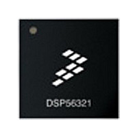
DSP56303VL100 Freescale Semiconductor, DSP56303VL100 Datasheet - Page 75

DSP56303VL100
Manufacturer Part Number
DSP56303VL100
Description
IC DSP 24BIT 100MHZ 196-MAPBGA
Manufacturer
Freescale Semiconductor
Series
DSP563xxr
Type
Fixed Pointr
Datasheet
1.DSP56303AG100.pdf
(108 pages)
Specifications of DSP56303VL100
Interface
Host Interface, SSI, SCI
Clock Rate
100MHz
Non-volatile Memory
ROM (576 B)
On-chip Ram
24kB
Voltage - I/o
3.30V
Voltage - Core
3.30V
Operating Temperature
-40°C ~ 100°C
Mounting Type
Surface Mount
Package / Case
196-MAPBGA
Device Core Size
24b
Format
Fixed Point
Clock Freq (max)
100MHz
Mips
100
Device Input Clock Speed
100MHz
Ram Size
24KB
Program Memory Size
Not RequiredKB
Operating Supply Voltage (typ)
3.3V
Operating Supply Voltage (min)
3V
Operating Supply Voltage (max)
3.6V
Operating Temp Range
-40C to 100C
Operating Temperature Classification
Industrial
Mounting
Surface Mount
Pin Count
196
Package Type
MA-BGA
Package
196MA-BGA
Maximum Speed
100 MHz
Device Million Instructions Per Second
100 MIPS
Lead Free Status / RoHS Status
Lead free / RoHS Compliant
Available stocks
Company
Part Number
Manufacturer
Quantity
Price
Company:
Part Number:
DSP56303VL100
Manufacturer:
FUJI
Quantity:
1 000
Company:
Part Number:
DSP56303VL100
Manufacturer:
FREESCALE
Quantity:
672
Company:
Part Number:
DSP56303VL100
Manufacturer:
Freescale Semiconductor
Quantity:
10 000
Company:
Part Number:
DSP56303VL100B1
Manufacturer:
Freescale Semiconductor
Quantity:
10 000
3.2 TQFP Package Mechanical Drawing
Freescale Semiconductor
Pin 1
ident
L
C
J
36
1
4X
0.08
Section J1-J1
144
37
(rotated 90)
0.20 T L-M
Figure 3-3.
144 PL
M
S1
D
F
A1
T L-M
N
N
A
S
Plating
Base
metal
AA
DSP56303 Mechanical Information, 144-pin TQFP Package
N
View Y
θ
θ
DSP56303 Technical Data, Rev. 11
2
2
4X 36 TIPS
C2
—
C1
109
72
0.05
View AB
108
CASE 918-03
73
T
0.20 T L-M
ISSUE C
M
(Y)
θ
View AB
0.1 T
B1 V1
Seating
plane
(Z)
144X
N
(K)
E
B
R2
V
R1
C L
Gage plane
0.25
θ
1
Notes:
TQFP Package Mechanical Drawing
1. Dimensions and tolerancing per ASME
2. Dimensions in millimeters.
3. Datums L, M and N to be determined at the
4. Dimensions S and V to be determined at
5. Dimensions A and B do not include mold
6. Dimension D does not include dambar
Y14.5, 1994.
seating plane, datum T.
the seating plane, datum T.
protrusion. Allowable protrusion is 0.25 per
side. Dimensions A and B do include mold
mismatch and are determined at datum
plane H.
protrusion. Allowable dambar protrusion
shall not cause the D dimension to exceed
0.35.
DIM
A1
B1
C1
C2
R1
R2
S1
V1
AA
θ
θ
A
B
C
D
E
F
G
K
P
S
V
Y
Z
θ
J
View Y
1
2
Millimeters
MIN
1.40
0.05
1.35
0.17
0.45
0.17
0.09
0.13
0.13
0.09
20.00 BSC
10.00 BSC
20.00 BSC
10.00 BSC
22.00 BSC
11.00 BSC
22.00 BSC
11.00 BSC
0.50 BSC
0.25 BSC
0.25 REF
1.00 REF
11°
0.50 REF
0°
0°
J1
J1
MAX
1.60
0.15
1.45
0.27
0.75
0.23
0.20
0.20
0.20
0.16
13°
140X
7°
4X
G
X=L, M or N
X
P
3-9


