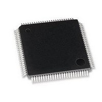
LAN9118-MD SMSC, LAN9118-MD Datasheet - Page 118

LAN9118-MD
Manufacturer Part Number
LAN9118-MD
Description
Ethernet ICs HiPerfrm Sngl-Chip 10/100 Ethrnt
Manufacturer
SMSC
Type
Single Chip MAC and PHYr
Datasheet
1.LAN9118-MT.pdf
(132 pages)
Specifications of LAN9118-MD
Ethernet Connection Type
10 Base-T, 100 Base-TX
Minimum Operating Temperature
0 C
Mounting Style
SMD/SMT
Product
Ethernet Controllers
Number Of Transceivers
1
Standard Supported
802.3
Data Rate
10 MB, 100 MB
Supply Voltage (max)
3.3 V
Supply Voltage (min)
0 V
Maximum Operating Temperature
+ 70 C
Package / Case
TQFP-100
Lead Free Status / RoHS Status
Lead free / RoHS Compliant
- Current page: 118 of 132
- Download datasheet (2Mb)
Revision 1.5 (07-11-08)
6.3
SYMBOL
nCS, nRD
t
t
t
t
t
t
t
t
csdv
acyc
t
asu
adv
don
doff
doh
csh
A[7:5]
A[4:1]
Data Bus
ah
In this mode, performance is improved by allowing up to 8, DWORD read cycles, or 16, WORD read
cycles back-to-back. PIO Burst Reads can be performed using Chip Select (nCS) or Read Enable
(nRD). Either or both of these control signals must go high between bursts for the period specified.
Timing for 16-bit and 32-bit PIO Burst Mode Read cycles is identical, with the exception that D[31:16]
are not driven during a 16-bit burst.
Note: The “Data Bus” width is 32 bits with optional support for 16-bit bus widths
Note: A PIO Burst Read cycle begins when both nCS and nRD are asserted. The cycle ends when
PIO Burst Reads
DESCRIPTION
nCS, nRD Deassertion Time
nCS, nRD Valid to Data Valid
Address Cycle Time
Address Setup to nCS, nRD valid
Address Stable to Data Valid
Address Hold Time
Data Buffer Turn On Time
Data Buffer Turn Off Time
Data Output Hold Time
either or both nCS and nRD are deasserted. They may be asserted and deasserted in any
order.
Figure 6.2 LAN9118 PIO Burst Read Cycle Timing
Table 6.4 PIO Burst Read Timing
DATASHEET
118
High Performance Single-Chip 10/100 Non-PCI Ethernet Controller
MIN
13
45
0
0
0
0
TYP
MAX
30
40
7
SMSC LAN9118
Datasheet
UNITS
ns
ns
ns
ns
ns
ns
ns
Related parts for LAN9118-MD
Image
Part Number
Description
Manufacturer
Datasheet
Request
R

Part Number:
Description:
IC ETHERNET CTRLR 10/100 100TQFP
Manufacturer:
SMSC
Datasheet:

Part Number:
Description:
MCU, MPU & DSP Development Tools Evaluation Board
Manufacturer:
SMSC

Part Number:
Description:
MCU, MPU & DSP Development Tools Evaluation Board
Manufacturer:
SMSC

Part Number:
Description:
FAST ETHERNET PHYSICAL LAYER DEVICE
Manufacturer:
SMSC Corporation
Datasheet:

Part Number:
Description:
357-036-542-201 CARDEDGE 36POS DL .156 BLK LOPRO
Manufacturer:
SMSC Corporation
Datasheet:

Part Number:
Description:
357-036-542-201 CARDEDGE 36POS DL .156 BLK LOPRO
Manufacturer:
SMSC Corporation
Datasheet:

Part Number:
Description:
357-036-542-201 CARDEDGE 36POS DL .156 BLK LOPRO
Manufacturer:
SMSC Corporation
Datasheet:

Part Number:
Description:
4-PORT USB2.0 HUB CONTROLLER
Manufacturer:
SMSC Corporation
Datasheet:

Part Number:
Description:
Manufacturer:
SMSC Corporation
Datasheet:

Part Number:
Description:
Manufacturer:
SMSC Corporation
Datasheet:

Part Number:
Description:
FDC37C672ENHANCED SUPER I/O CONTROLLER WITH FAST IR
Manufacturer:
SMSC Corporation
Datasheet:

Part Number:
Description:
COM90C66LJPARCNET Controller/Transceiver with AT Interface and On-Chip RAM
Manufacturer:
SMSC Corporation
Datasheet:

Part Number:
Description:
Manufacturer:
SMSC Corporation
Datasheet:

Part Number:
Description:
Manufacturer:
SMSC Corporation
Datasheet:


